EN

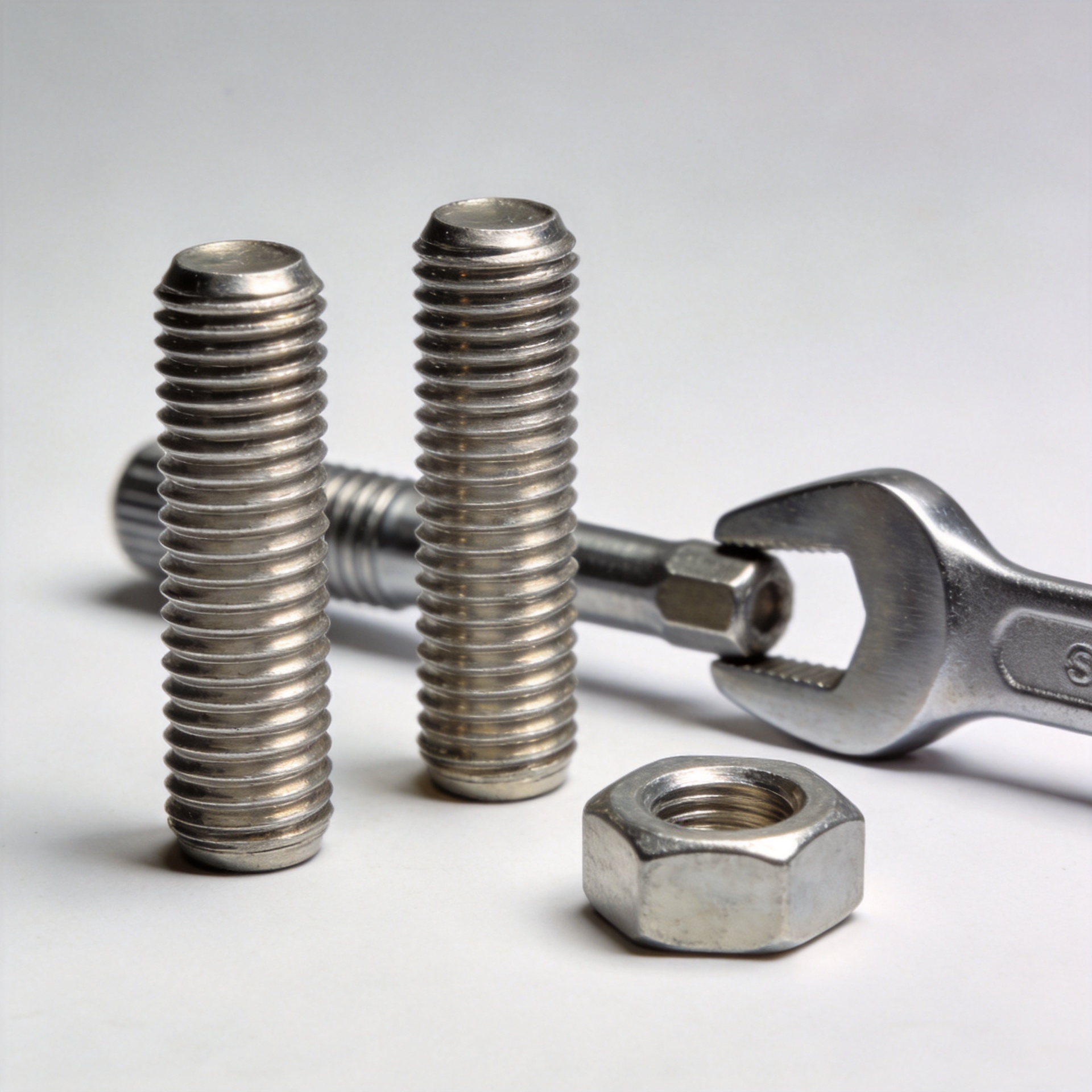
How to Address Stud Thread Galling in Stainless Steel Assemblies
Stainless steel Studs are often specified for corrosion resistance, serviceability, and clean-looking assemblies. Yet the same stainless-on-stainless contact that suits a corrosive environment can create a costly assembly interruption: thread galling. A nut that suddenly tightens, locks, or twists a threaded stud during installation is not simply an operator inconvenience. It can damage both mating threads, distort the intended clamp load, and turn a removable joint into a rework task.
As a fastening-selection engineer, I start with the joint rather than blaming a single part. Studs, nuts, tapped holes, surface condition, tool speed, and torque procedure interact. The practical goal is to reduce the conditions that promote adhesive wear while still achieving the preload the joint needs. This article offers a controlled way to diagnose the problem and improve the assembly process.
What thread galling means for stainless steel Studs
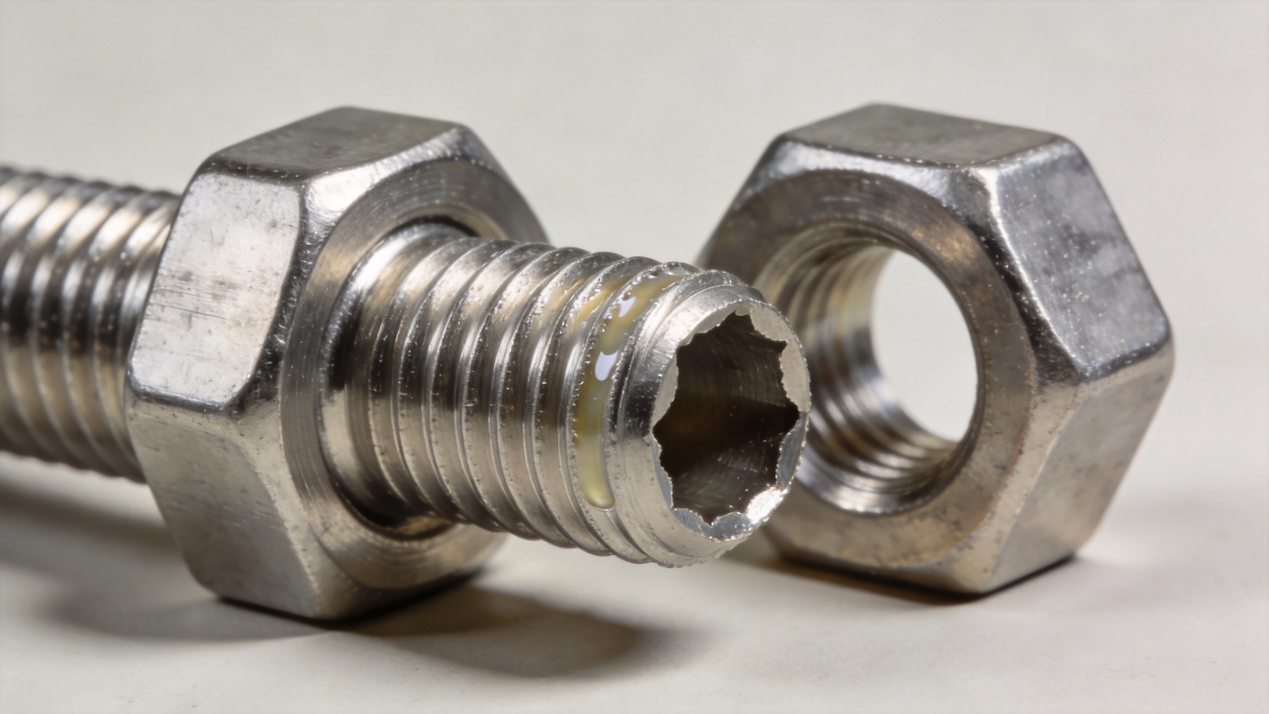
Thread galling is severe adhesive wear between moving thread flanks. During tightening, microscopic high points on the mating surfaces slide under load. If the protective surface film breaks down and local friction and heat rise, metal can transfer between the two threads. The torque may climb abruptly, the parts may seize, and continued turning can strip threads or twist the fastener.
Stainless steel Studs are more susceptible when both mating members are similar austenitic stainless grades, but material pairing alone does not explain every event. A double ended stud installed into a tapped component, for example, may experience resistance at one end before the nut is even loaded. A stud bolt can gall at the nut end if its threads are damaged, dry, or driven too quickly. The useful question is: where did resistance begin, and what changed immediately before it did?
Start with a disciplined diagnosis
Do not keep applying torque after a stainless fastener begins to bind unexpectedly. Stop the cycle, mark the parts, and inspect both sides. Continuing to turn Studs after the torque signature changes can convert a small damaged area into a seized joint.
Check the evidence in this order
- Separate the parts if safe to do so. Look for torn metal, raised material, scoring, discoloration, or thread flattening on the male and female threads. Do not return visibly damaged Studs to the assembly bin.
- Identify the location. Determine whether the issue occurred while seating a double ended stud, while running a nut on a stud bolt, or at a threaded insert. The location helps separate alignment and fit-up issues from final-torque issues.
- Inspect cleanliness and starting engagement. Chips, abrasive grit, plating debris, burrs, and handling contamination change friction. Verify that Studs can start squarely by hand for several turns when the application permits.
- Review the tightening trace. Compare the recorded torque-angle behavior, tool speed, and shutoff setting with a known-good assembly. An early torque rise often points to prevailing resistance, misalignment, or thread damage rather than normal joint clamp-up.
- Compare the mating materials and condition. Record grade, finish, lubrication status, thread class, and whether the batch contains mixed surface conditions. This record matters before changing a torque value.
Common conditions that raise galling risk
Galling is rarely random. The following conditions can combine around Studs and increase frictional heating or concentrate contact on a small area.
- Misalignment: If parts are pulled together by the fastener instead of being aligned before tightening, a threaded stud can enter at an angle. Contact is then concentrated instead of shared across the engaged flanks.
- Damaged, dirty, or poorly deburred threads: A nick, burr, or embedded particle can start localized adhesion. Gauge inspection and clean handling are process controls, not cosmetic checks.
- High installation speed: Faster rotation leaves less time for generated heat to dissipate. Use a controlled rundown speed and reserve final tightening for a validated process.
- Excessive torque or yield: More torque does not automatically mean a safer joint. If the actual thread condition changes, the same torque can produce a different tension and may overload the contact surfaces.
- Long rotation under resistance: Prevailing-torque features, excessive protrusion, or a soft joint can make the threads slide under load for longer. Review the full tightening cycle rather than the final torque alone.
A welding stud assembly deserves the same discipline. Heat input from welding, spatter, distortion, or a damaged start thread may affect the subsequent nut-running operation. Inspect the usable thread zone and fixture alignment before attributing the event to the nut alone.
Build a controlled assembly method for Studs
The most reliable response is a process package, not a single remedy. First, specify how incoming Studs and mating components are checked: thread gauge results, visual acceptance, lot identity, cleanliness, and approved surface condition. Next, define the installation sequence. Components should be brought into alignment before the fastener is asked to draw them together. In multi-fastener joints, start all locations and use a sequence that avoids creating a gap the remaining fasteners must close.
Then control speed. Use a low, repeatable rundown speed for stainless assemblies and stop if torque rises before the expected seating point. An impact tool or an uncontrolled high-speed driver can obscure the first warning sign. For a stud bolt joint that is assembled and removed repeatedly, include removal behavior in the validation plan; a process that runs once may not reflect service exposure.
Where the engineering review supports it, use an approved lubricant, anti-seize, dry-film treatment, or dissimilar mating condition. Apply it consistently to the defined surface, not opportunistically at the station. These measures can lower friction, but they also change the torque-tension relationship. The dry torque target must therefore not be carried over unchanged. Validate the new condition with the applicable joint, fastener grade, engagement length, and tightening method.
Choose the remedy based on the failure pattern
| Observed pattern | Likely focus | Next controlled action |
|---|---|---|
| Binding begins before seating | Alignment, contamination, starting thread, or fit | Check fixturing, hand-start capability, gauges, and thread cleanliness. |
| Binding appears near final torque | Friction, speed, torque setting, or surface condition | Review torque-angle data and validate a defined lubricant or finish condition. |
| Only one end of a double ended stud is affected | Different mating geometry or installation sequence | Inspect the affected internal thread and the seating method independently. |
| Failures follow welding or fabrication | Thread damage, distortion, or spatter | Protect and gauge the usable threads after fabrication; review fixture alignment. |
This table is a screening tool, not a substitute for joint testing. If a change to Studs, coatings, lubricants, or torque procedure is proposed, document the actual assembly condition and verify clamp load, installation behavior, and service requirements together.
When material or geometry should be reviewed
Some stainless applications retain galling risk even after cleaning, alignment, and speed controls improve. Repeated adjustment, high prevailing torque, very fine pitch, long engagement, or demanding temperature exposure may justify a design review. Options can include a different grade or hardness relationship, a qualified coating, a specified dry film, or a revised thread and engagement design. The appropriate choice depends on corrosion exposure, load, temperature, required reuse, and the available validation method.
Do not switch a threaded stud or welding stud material solely because one assembly seized. First establish whether the root condition was mixed lubrication, an out-of-square mating component, damaged threads, or a tool setting. Conversely, do not assume process controls alone will be enough when a design repeatedly creates high sliding resistance. The decision should be based on evidence from the real assembly.
A practical release checklist
- Specify compatible grades, thread form, engagement, finish, and approved condition for all Studs.
- Set acceptance checks for thread damage, contamination, and gauge condition before installation.
- Align components before a threaded stud or nut is tightened to final load.
- Use controlled low-speed rundown and monitor unexpected torque rise.
- Define lubricant, coating, or anti-seize application when the process requires it.
- Revalidate torque or angle targets whenever friction condition, finish, or mating material changes.
- Quarantine galled components and inspect both mating threads before deciding on rework.
Conclusion
Thread galling in stainless assemblies is a joint-level problem with visible process clues. By inspecting the damaged thread contact area, separating early-running resistance from final-tightening resistance, controlling alignment and speed, and validating the torque condition after any friction change, teams can reduce recurring losses around Studs. The right solution may involve handling, tooling, lubrication, geometry, or material selection; the durable answer comes from testing the actual assembly condition rather than applying a generic torque adjustment.