EN

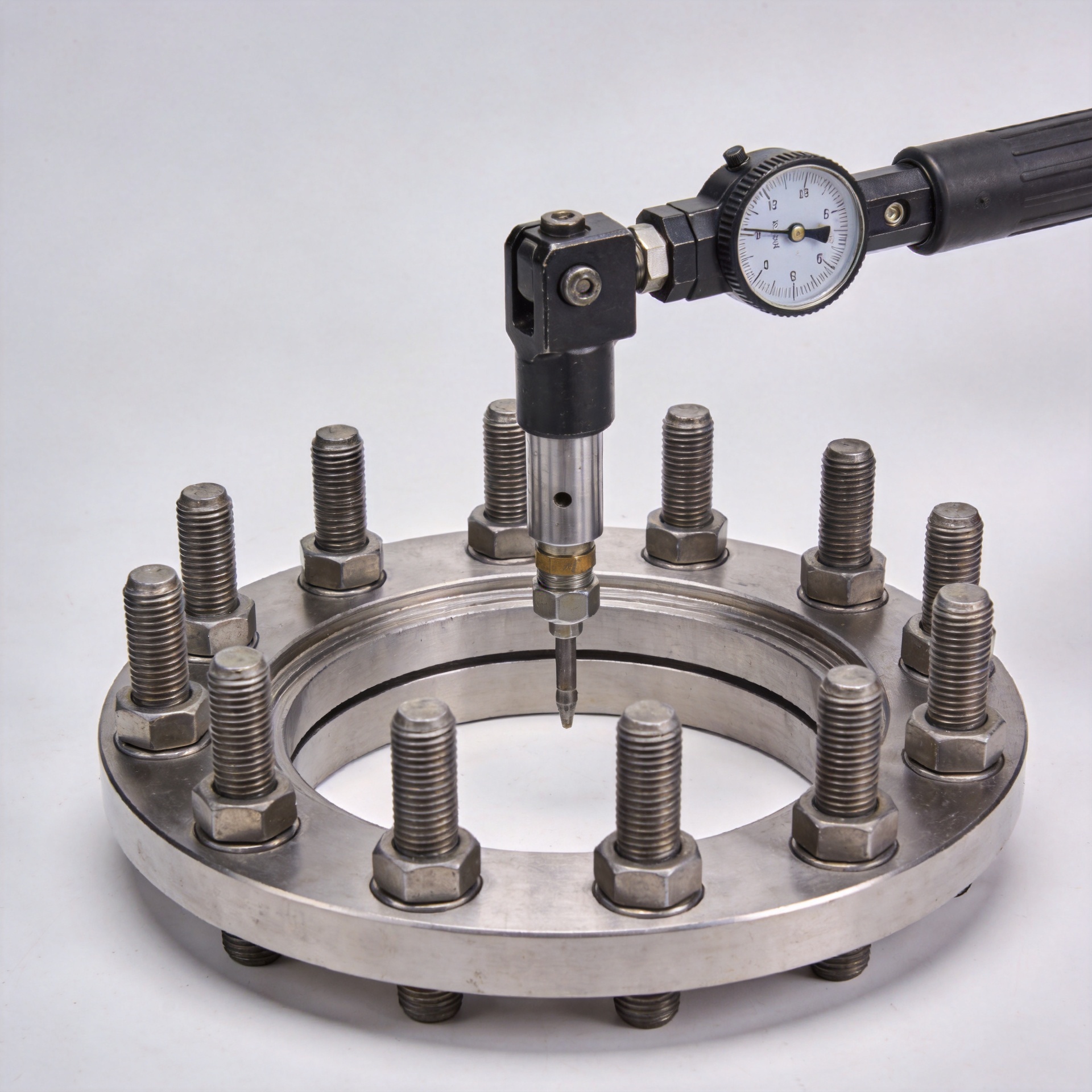
How to Solve Uneven Stud Tension in Multi Bolt Flange Connections
Uneven tension across flange studs is a joint-assembly problem, not just a torque-wrench problem. When some studs carry much more load than others, gasket compression becomes nonuniform. The result can be leakage, flange rotation, damaged threads, or an assembly that changes load after the crew leaves. This guide gives maintenance teams a practical way to diagnose uneven stud tension and correct the process under the approved joint procedure.
The important starting point is simple: a final torque reading does not prove equal load in every stud. Torque is an indirect input, while the working objective is a controlled and reasonably uniform clamping load around the gasket. The applicable engineering specification, flange standard, gasket supplier guidance, and site bolting procedure remain the governing documents for each joint.
Why multi-bolt flange studs lose tension balance
A flange joint behaves as a system. Tightening one of the studs compresses the gasket and moves the flange faces slightly. That movement can reduce the load in adjacent studs that were tightened earlier. This mechanical interaction is why a single pass around the circumference often leaves the first studs with lower residual load and the last studs with higher load.
Several conditions make the imbalance worse:
- A circular tightening order is used before the gasket is seated evenly.
- The flange faces are not parallel, or the initial gap differs around the circumference.
- Lubrication, nut condition, or thread condition varies from one stud to another.
- Stud length, engagement, material, or washer arrangement is mixed within the joint.
- A crew uses one target torque despite different friction conditions on the studs.
- The gasket is displaced, damaged, or not centered before tightening begins.
In practice, a threaded stud that turns freely with a compatible nut and controlled lubricant can respond differently from a dry, corroded, or damaged one. A double ended stud also needs correct engagement at both ends; unequal engagement changes the assembly behavior and can complicate inspection. These are setup issues to resolve before treating the torque value as the root cause.
Start with a safe diagnostic check
Do not attempt to equalize studs on an energized or pressurized flange unless the site procedure explicitly permits that work. Isolate the equipment, follow the applicable permit and lockout requirements, and confirm the joint can be opened or retightened safely. For critical process service, involve the responsible engineer or qualified bolting specialist before changing a tightening plan.
With the joint in an approved maintenance condition, inspect the circumference rather than focusing on one loose-looking nut. Record the flange gap at several positions, identify the installed studs and nuts, and note whether all threads, washers, and bearing surfaces are comparable. A visible gap difference, a tilted nut, or a stud with less thread engagement than its neighbors is useful evidence. It is not a reason to force that one location to the target value while leaving the rest unchanged.
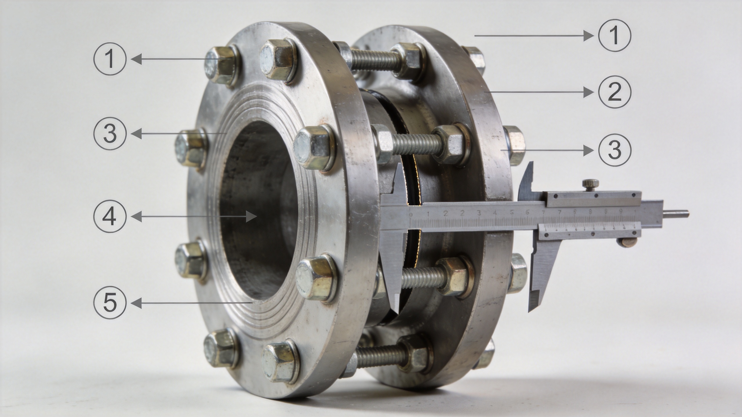
Check the parts before changing the sequence
Verify the stud-and-nut combination
Confirm that all studs match the drawing or bill of materials for diameter, pitch, grade, coating, and length. Check that nuts run freely by hand over the usable thread before assembly. Remove damaged, stretched, heavily corroded, or mixed fasteners from service according to the project rules. A welding stud is designed for a different attachment method and should not be substituted into a pressure-boundary flange joint unless the engineering design specifically calls for it.
Also examine thread engagement. A stud that bottoms out, carries a nut on incomplete threads, or has dramatically different projection can introduce a local problem that a better pattern alone will not correct. When replacement is necessary, obtain traceable parts that match the specification instead of assembling a mixed set of studs.
Inspect joint geometry and gasket position
Clean flange faces using the approved method and inspect for damage that may affect seating. Confirm alignment without using the studs to pull severely misaligned pipe into position. Align the gasket concentrically and make sure it is suitable for the service. If the gap cannot be brought reasonably uniform at the snug stage, pause and correct the underlying alignment issue. Continuing with higher load can lock in uneven gasket compression.
Use a controlled multi-pass tightening method
For conventional single-tool assembly, a cross or star pattern brings opposed areas of the flange together gradually. The exact numbered pattern depends on bolt count and the governing procedure. The purpose is to distribute movement, not to chase one high or low reading. Industry guidance such as ASME PCC-1 describes staged pattern passes at a low portion of the approved target, then an intermediate portion, then the specified final level, with a circular verification pass after the pattern work.
- Snug the studs evenly. Bring nuts into contact using the approved initial-load method. Check that the flange gap is reasonably even around the full circumference.
- Run the first cross-pattern pass. Apply the project procedure’s lower pass value to the numbered pattern. Recheck parallelism and gasket position.
- Run the intermediate pattern pass. Repeat the same pattern at the next approved level. If the gap is becoming uneven, stop and investigate geometry, friction, or component mismatch.
- Run the final pattern pass. Apply the specified target by the same pattern and tool-control method.
- Verify around the circle. Make circular check passes at the final setpoint until the procedure’s acceptance condition is met. This is where earlier studs are brought back into balance after load redistribution.
The percentages and number of passes must come from the approved joint procedure, not from a generic table. Large diameters, sensitive gaskets, high-pressure service, and flange designs with significant movement may require additional pattern or check passes. The technician’s notes should show the tool, lubricant condition, sequence, target, and final verification result for the assembled studs.
When torque control is not giving repeatable stud tension
Torque has to overcome thread and bearing-surface friction before it can stretch studs. That means a change in coating, lubricant amount, nut surface, or thread damage can change achieved tension even when the displayed torque does not change. If repeated assemblies show an uneven pattern, investigate friction control before simply increasing the torque.
For suitable critical joints, an engineered hydraulic tensioning method can reduce torsional effects and load several studs in a planned pattern. It still requires a qualified procedure, compatible tooling, calculated load factors, and flange-gap checks. It is not an automatic substitute for preparation. The same discipline applies: inspect the studs, align the flange, control the sequence, and verify the final condition.
A practical troubleshooting map
| Observed condition | Likely contributor | Useful next action |
|---|---|---|
| Early studs are loose after the last nuts are tightened | Elastic interaction during assembly | Repeat approved pattern and final circular verification passes. |
| One sector has a larger flange gap | Misalignment, gasket position, or uneven initial closure | Return to the approved low-load stage and correct geometry before advancing. |
| Torque response differs between studs | Inconsistent lubrication or damaged threads | Inspect, clean, replace as specified, and standardize the approved lubricant process. |
| A single nut binds or will not seat | Thread damage, mismatch, or poor engagement | Do not force it; inspect the nut and threaded stud against the drawing. |
Record what was installed
On a repeat repair, identify each set of studs by size, grade, coating, and lot where that information is available. Note whether the assembly uses a threaded stud, a double ended stud, or another specified form. Keep welding stud hardware out of the pressure-boundary bill unless the design identifies that application. For every stud bolt location, record the nut, washer, lubricant, and measured condition. This simple record makes it easier to distinguish a stud issue from a tooling or sequence issue on the next shutdown.
Build repeatability into future flange work
Reliable flange assembly begins before the wrench is applied. Store studs to limit corrosion, segregate grades and sizes, use a documented lubrication practice, and mark the sequence so each technician follows the same pattern. For water-pipeline, valve, and petrochemical equipment work, procurement teams should also request the required material documents and verify that delivered studs correspond to the intended service conditions.
Qingdao Jeekuu Hardware Products Co., Ltd. supports technical communication for fastener specification and application matching. For a new or replacement stud package, share the drawing, material requirement, thread standard, operating environment, and required documentation so the component selection can be reviewed against the actual joint rather than selected by appearance alone.
Key takeaway
Uneven tension in flange studs is usually a system signal: joint geometry, friction, component condition, tightening order, and elastic interaction all matter. Reset the work at the right stage, inspect the studs and gasket arrangement, use the approved cross-pattern passes, and complete the prescribed verification passes. That approach gives the joint a sounder basis for uniform gasket compression and documented maintenance control.