EN

How to Stop Anchor Edge Failure in Close to Edge Anchor Setups
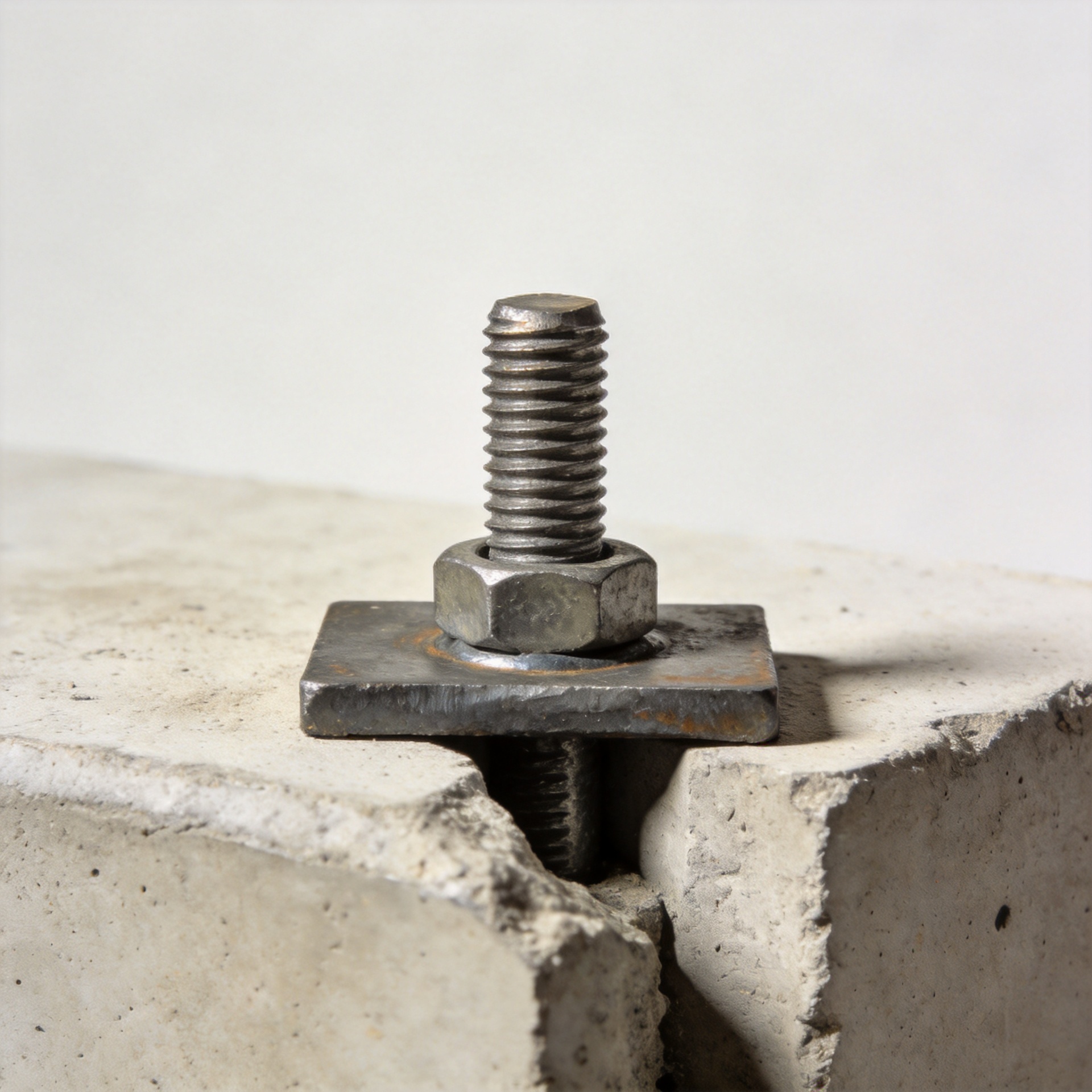
An Anchor installed near a concrete edge is not a routine fastening decision. The nearby free face changes how the base material can resist load, particularly when shear acts toward that edge. A close-to-edge Anchor can still be workable, but only when the selected system, layout, concrete condition, load path, and installation controls are evaluated together.
From a fastener-selection engineer’s viewpoint, the first question is not “Which Anchor is strongest?” It is “What failure mode governs this exact connection?” A high-strength steel element does not restore concrete that has too little breakout capacity. This article offers a practical screen for project teams before a hole is drilled; final design decisions should use the current approval data and the applicable project design standard.
Why an Anchor Near an Edge Behaves Differently
Concrete transfers an Anchor load into a volume of surrounding material. Under tension, that volume may form a breakout cone. Under shear directed toward a free edge, the potential breakout path is truncated by the edge. Less engaged concrete can mean a lower available resistance than the same Anchor would have in a wide slab.
This is why a drawing dimension alone is not enough. Edge distance, embedment, Anchor diameter, concrete thickness, concrete strength, cracking condition, nearby reinforcement, group spacing, and the direction of the applied load all influence the check. For a bracket carrying eccentric load, even a modest change in lever arm can increase tension in one Anchor while another sees shear toward the edge.
Do not convert a generic “diameters from the edge” rule into a universal release criterion. A rule of thumb may flag a connection for further review, but it cannot replace the published design data for the actual Anchor, installation method, and base material.
Start With the Actual Failure Scenario
Before choosing a Anchor, document the connection rather than relying on a product category. Record the following items in the field survey and design review:
- the measured centerline-to-edge distance in every relevant direction;
- the concrete member thickness, visible defects, joints, and distance to adjacent openings;
- factored tension, shear, and combined loading, including the direction of shear;
- the fixture geometry, stand-off, slots, and whether the load can introduce prying or rotation;
- the proposed Anchor spacing and whether breakout zones may overlap; and
- the concrete condition assumed by the selected system, including cracked or uncracked status where applicable.
This list separates an Anchor selection from an Anchor design. It also makes late conflicts visible: a rebar obstruction, a narrow pedestal, or a slot that permits fixture movement can invalidate an otherwise reasonable installation plan.
Use the Load Direction to Choose the Remedy
Shear directed toward the free edge
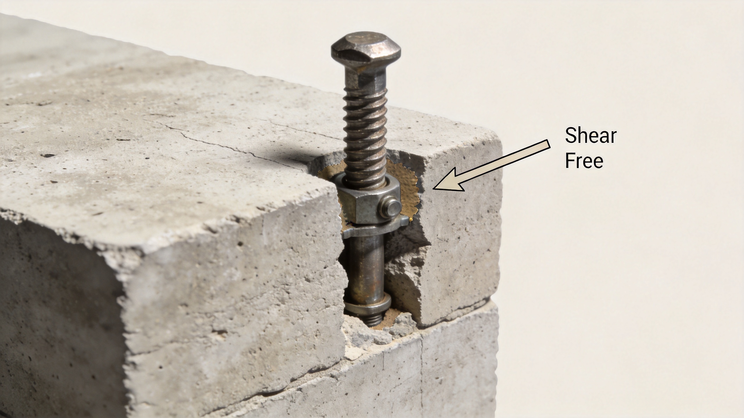
When a horizontal force pushes an Anchor toward the nearest edge, concrete edge breakout is often the issue that deserves early attention. The preferred remedy may be to move the connection inward, change the bracket so the shear line changes, add a designed shear lug, or distribute load through a revised base plate. Simply increasing Anchor diameter may not solve an edge-governed concrete check and can make installation more demanding.
Tension and prying
Tension can arise from direct uplift, overturning, or a flexible fixture that pries on the fasteners. In that case, assess each Anchor position, not just total group load. A thicker or stiffer connection plate can reduce unintended prying, while a layout change can relocate the heavily tensioned Anchor farther from a constrained edge.
Combined action
Close-edge work frequently combines shear, tension, and installation tolerance. Treating each demand in isolation can miss the governing interaction. Use the selected Anchor system’s current design method to check the combination and the reductions associated with the actual geometry.
Match the Anchor Type to the Verified Geometry
A wedge anchor develops mechanical expansion in drilled concrete. It can be appropriate where its approved edge-distance, spacing, embedment, load, and concrete-condition limits fit the connection. Near an edge, the expansion mechanism and installation torque require careful attention; do not substitute field judgment for the manufacturer’s approved limits.
A sleeve anchor is often considered for light-to-medium duty attachments and can suit some hollow or solid masonry applications depending on the specific product. Its suitability for a close-edge connection still depends on published data and the base material actually present. “It is a sleeve anchor” is not a capacity calculation.
A concrete anchor selected for limited edge distance may require a different approved system, a different diameter or embedment range, or a revised layout. An adhesive, screw-type, undercut, or mechanical system each has its own installation and design restrictions. The category name does not establish performance.
A drop in anchor is an internally threaded option used in appropriate solid concrete applications. It can simplify a removable fixture, but its use near an edge must still be verified against the specific product data, installation depth, and loading direction. Select the Anchor only after the geometry and demand are known.
Installation Controls That Matter Near an Edge
- Lay out before drilling. Mark the centerline, edge, and fixture position. Check that field dimensions match the approved layout.
- Scan where required. Locate reinforcement, conduits, and embedded items under the project’s approved procedure. Do not shift an Anchor casually to bypass an obstruction.
- Drill to the prescribed diameter and depth. Hole size and embedment are part of the approved Anchor system, not optional workmanship details.
- Clean the hole as specified. Dust can change how some anchor systems engage the base material. Follow the applicable drilling and cleaning sequence.
- Install and tighten to the stated procedure. Record torque, setting action, adhesive-setting conditions, or inspection points when the approved system calls for them.
- Stop for an engineering review when dimensions change. A smaller measured edge distance, unexpected cracking, or an altered load path is a design change.
A Practical Close-Edge Anchor Decision Sequence
Use this sequence before procurement or installation. First, measure the member and identify the nearest free edges. Second, obtain the connection loads and directions from the responsible designer. Third, shortlist an Anchor system only where the current technical documentation covers the concrete condition and geometry. Fourth, check steel strength, pullout or bond where relevant, concrete breakout, pryout, and combined loading under the governing design method. Fifth, revise the connection if the edge check governs; moving the fixture, adding a structural load-transfer feature, or changing the connection concept is often more reliable than forcing a fastener into an unsuitable location.
For international construction and steel-structure supply chains, clear information flow matters as much as the Anchor itself. Send the installer an approved drawing, the product installation instructions, inspection hold points, and a record template. Qingdao Jeekuu Hardware Products Co., Ltd. supports broader fastener sourcing discussions, while the responsible engineer should retain control of the project-specific Anchor design and approval check.
Conclusion: Treat Edge Distance as a Design Input
Close-to-edge Anchor setups deserve a design-led response. Identify the likely breakout direction, quantify the real loads, verify the base material, and use the exact system’s current design data. If the geometry cannot support the proposed Anchor, revise the connection rather than treating installation as a workaround. That discipline reduces uncertainty before a small drilling decision becomes a concrete repair problem.