EN

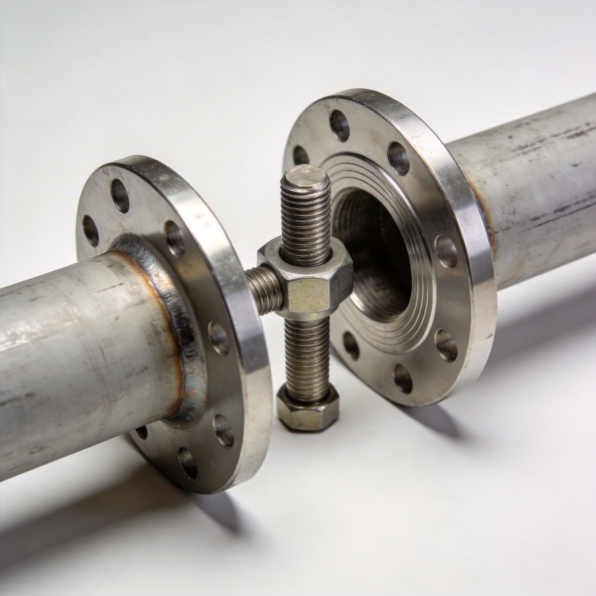
How to Stop Fastener Loosening in Industrial Pipeline Flange Service
A leaking pipeline flange is often treated as a gasket problem. In practice, the fastener system is just as important: it must maintain enough, reasonably uniform clamp load to keep the gasket seated as pressure, temperature, vibration, and maintenance conditions change. A threaded fastener can lose useful load long before anyone sees a loose nut. The practical response is not to add a locking device at random; it is to find out why clamp load was lost and correct the assembly method, components, or joint design under an approved site procedure.
A fastener-selection review begins with service load, joint stiffness, installation control, and resistance to loosening. A pipeline flange deserves a different approach from a lightly loaded machine cover. The joint may be safety-critical, and any work on pressurized equipment must follow the owner’s isolation, permitting, and engineering requirements.
Start with clamp load, not the nut that appears loose
A flange joint seals because the bolts or studs stretch and compress the flange, gasket, and other joint members. That stored stretch creates clamp load. If clamp load becomes uneven or falls below the gasket’s required seating range, the joint can leak even when every nut still appears to be in place.
Several mechanisms can reduce that load:
- Embedment and settlement: coatings, surface roughness, washer interfaces, thread contact, and gasket compression can settle after initial tightening.
- Elastic interaction: tightening one fastener changes the joint compression near the next location, relaxing fasteners that were tightened earlier.
- Thermal movement: different expansion rates among studs, flanges, and gasket materials can alter load during heat-up and cool-down.
- Vibration or joint slip: movement across the joint can rotate a nut or reduce preload, particularly where alignment or support problems remain unresolved.
- Corrosion and damaged threads: friction becomes inconsistent, so a torque reading no longer gives a consistent indication of stud tension.
For that reason, simply applying more torque to one suspected fastener is rarely a sound field solution. It can distort the flange, overload the gasket locally, or conceal a broader assembly-control issue.
Use the same fastener language in the work package
For every flange work order, identify the fastener set by size, grade, material, thread form, and coating rather than using a generic “bolt” description. That discipline helps a crew distinguish a threaded fastener specified for a pressure joint from hardware intended for a lighter attachment. It also makes later comparison possible when one fastener lot behaves differently after a shutdown.
A mechanical fastener selection should be reviewed with the flange, gasket, and tightening method as one system. The mechanical fastener is only one part of the load path, so a change in nut finish, washer arrangement, or lubricant may change the relationship between applied torque and clamp load. Where corrosion or process exposure is present, document whether the stainless fastener grade, mating material, and approved lubricant are suitable for the actual service temperature and chemical environment.
Custom fastener requirements deserve the same control. A custom fastener may be needed for stud length, unusual thread engagement, coating, or material compatibility, but its dimensions and certification should be checked against the approved joint design before use. Do not assume that a threaded fastener with a similar appearance has the required strength or thread tolerance. Treat every mechanical fastener substitution as an engineering decision, especially where a stainless fastener is being introduced to an existing carbon-steel joint.
Inspect the whole flange assembly before tightening
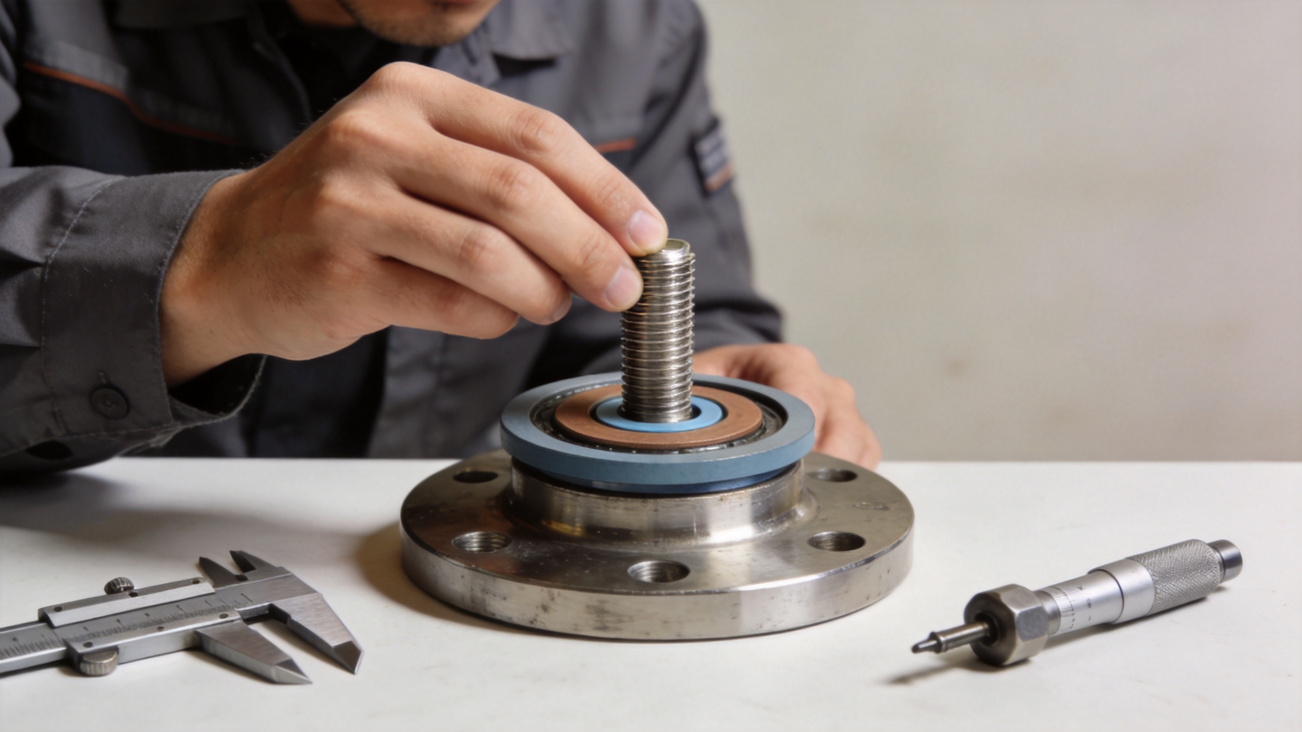
Begin only when the joint is safely isolated and the applicable procedure permits disassembly or adjustment. Check flange-face condition, parallelism, gasket type and centering, stud protrusion, nut engagement, thread damage, and evidence of corrosion. Look for piping strain, unsupported weight, or misalignment that forces the flanges together. A mechanical fastener is not intended to pull severely misaligned piping into position.
Also verify the actual components against the joint documentation. Stud material, grade, diameter, thread form, nut grade, washers, lubricant, gasket, flange rating, and target tightening method work as a system. A stainless fastener may be appropriate for a corrosive environment, but stainless-on-stainless thread contact can gall unless the material pairing, surface condition, and approved lubricant are considered. Changing only one element without engineering review can make torque-to-tension behavior less predictable.
Use a controlled multi-pass tightening sequence
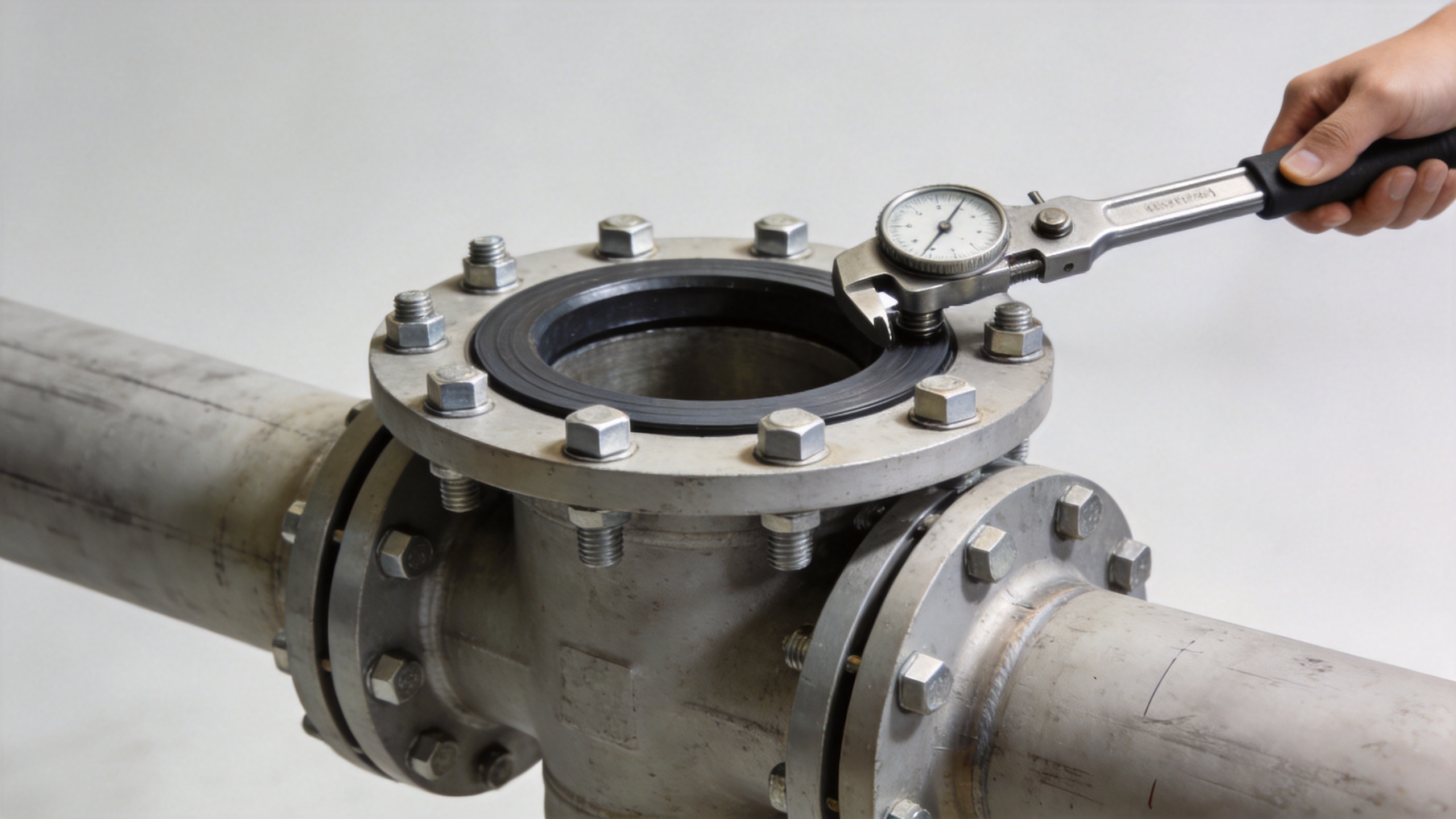
For pressure-boundary flange work, use the owner’s approved bolt-up procedure and the target load or torque calculated for that exact joint. ASME PCC-1 guidance describes an incremental approach: bring the joint together evenly, then tighten in multiple cross-pattern passes at increasing portions of the final target before using a circular check pass. The purpose is to seat the gasket uniformly and manage the elastic interaction between positions.
- Prepare and identify the fastener set. Use only components accepted for the job. Clean threads and bearing surfaces as the procedure requires, and apply the specified lubricant consistently. Mark or number the tightening order so the crew can follow it without guessing.
- Snug the joint evenly. Hand-tighten, then use the specified low-load pass to bring the faces together while checking that the flange gap remains reasonably uniform around the circumference.
- Increase load in a cross pattern. Use the documented sequence and staged targets. A cross pattern distributes the seating action instead of pulling one side down first.
- Complete the final target pass. Achieve the approved final value using calibrated equipment and the selected method, such as controlled torque, hydraulic torque, or tensioning where specified.
- Make a circular verification pass. At the final target, move around the flange as the procedure directs until additional nut rotation is no longer observed. Where allowed, a later recheck may address short-term settlement.
Use the exact percentages and sequence in the approved work package, not a generic chart. Torque is affected by lubrication and friction, so the same torque value can create different fastener tension when conditions change.
Choose locking features only after the preload problem is understood
Locking hardware can be useful, but it is not a substitute for adequate preload or correct gasket compression. Depending on the service, the engineered solution may include a locking nut, all-metal prevailing-torque feature, wedge-lock washer arrangement, double-nutting method, or a different bolting and tensioning method. The selection must consider temperature, corrosion, access, repeat assembly, material compatibility, and the governing piping or pressure-boundary specification.
A threaded fastener used with a locking element still needs proper engagement and controlled installation. If the joint is slipping because of pipe movement, flange rotation, or uneven face contact, the locking feature may only delay the visible symptom. Address the movement source first.
Build a maintenance record that helps the next crew
A reliable flange program records more than a final torque value. Capture the joint ID, fastener and gasket specification, lubricant, tool ID and calibration state, sequence used, target method, assembler, date, service condition, and any deviations found during inspection. For recurring leak locations, compare records across shutdowns. Patterns often reveal whether the issue follows a material lot, a particular gasket family, a line support condition, thermal cycle, or inconsistent work practice.
Competent assembly is a control in its own right. Standards such as EN 1591-4 focus on competency for personnel who assemble bolted joints in pressurized systems. Training does not replace an engineering procedure, but it helps crews recognize flange misalignment, damaged threads, incorrect sequence use, and unsafe attempts to retighten live equipment.
A practical decision checklist
- Confirm the joint is isolated and the work is authorized.
- Check flange alignment, face condition, gasket position, and piping loads before reassembly.
- Match every fastener component and lubricant to the approved joint specification.
- Use calibrated tools, a documented cross pattern, staged loading, and a final check pass.
- Investigate corrosion, galling, vibration, thermal cycling, and settlement rather than relying only on a locking device.
- Escalate repeat leaks or critical-service joints to the responsible engineer for a joint-specific review.
Stopping fastener loosening in industrial pipeline flange service is fundamentally a clamp-load management task. When the flange is aligned, the gasket is seated evenly, the mechanical fastener set is compatible, and tightening is controlled and recorded, the joint is in a far stronger position to hold its intended load through service.