EN

Why Fastener Threads Strip in Soft Materials and How to Reduce the Risk
A stripped thread rarely begins at the instant a driver slips. In soft aluminum, plastics, wood-based panels, thin sheet, or zinc die castings, the joint has a limited amount of material available to carry load. Once installation torque exceeds that material’s thread shear capacity, the fastener can turn without building clamp load. The response is not simply to tighten harder. It is to match the fastener, hole preparation, engagement, and installation method to the substrate.
A fastener selection engineer will usually ask: what is the weakest part of this joint under the actual assembly conditions? Often it is the internal thread in the soft component rather than the external thread on the screw. That distinction changes how a threaded fastener should be specified and installed.
What thread stripping looks like in a soft-material joint
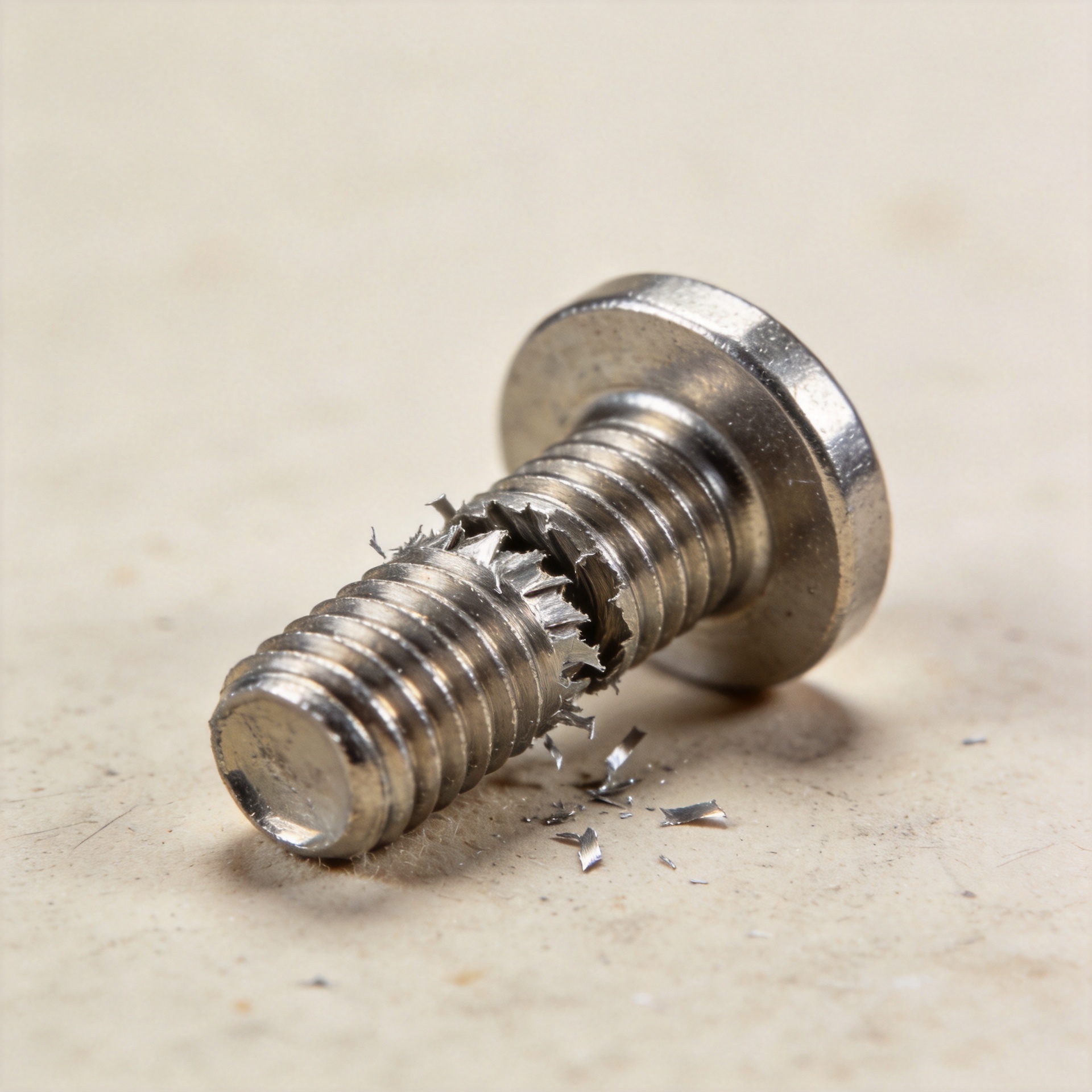
Thread stripping occurs when the material around the mating thread shears or deforms enough that the fastener no longer advances or holds the intended preload. It may show up as a sudden drop in resistance, a screw that spins freely, a joint that loosens shortly after assembly, or a hole that accepts the screw but will not retain it during service.
A mechanical fastener can be strong in tension and still fail this way because joint strength depends on the thread-contact zone. Soft substrates provide less bearing area, may creep under sustained load, and can be damaged by an oversized pilot hole or repeated service. Thin sections compound the problem because there are fewer engaged threads to distribute load.
Why fastener threads strip
Too little usable thread engagement
Engagement length is the material depth that actually supports the thread. A fastener entering a thin wall, shallow boss, or short tapped section has less shear area than one seated in a deeper section. Blind-hole bottoms, chamfers, paint, burrs, and incomplete tapping can reduce usable engagement further. Adding torque cannot create missing engagement; it merely raises the chance that the available material will yield.
A pilot hole that does not match the thread-forming method
For a thread-forming fastener, the pilot hole must leave enough substrate for the thread to displace and form a stable mating profile. If the hole is too large, the thread has little material to grip. If it is too small, driving torque rises sharply and the surrounding material may crack, distort, or tear. A thread-cutting design needs its own hole and material considerations because it removes or displaces material differently. Treat pilot-hole size as a controlled assembly variable, not a rough drill choice.
Torque applied beyond the joint’s capacity
Torque has two jobs: overcoming friction and developing clamp load. In a soft-material joint, the thread can reach its shear limit before the desired clamp load is achieved. This is common when a power tool is set from experience with steel hardware, when lubrication changes friction unexpectedly, or when operators continue driving after the head seats. A stainless fastener may also change friction behavior from one surface condition to another, so a torque setting that worked on a previous build should be verified on the current stack-up.
Misalignment and side loading during installation
Starting a fastener at an angle cuts an uneven path and concentrates force on one side of the hole. A worn bit, poor fixture access, or a driver that wobbles can produce the same effect. The resulting threads may look acceptable at first but have reduced contact area. Side loads in service can then finish the damage, especially in assemblies that are opened and reclosed.
Material behavior over time
Some plastics relax under load, and soft metals can deform when a joint sees heat cycles, vibration, or frequent disassembly. The original installation may feel secure while clamp load diminishes later. For that reason, a custom fastener program should consider material grade, wall thickness, expected service temperature, and the number of assembly cycles rather than using one screw pattern across unrelated components.
A practical prevention sequence
- Define the substrate first. Record the material, thickness, boss geometry, and whether the hole is molded, drilled, punched, or tapped. These details determine whether a thread-forming, thread-cutting, machine-threaded, or insert-based approach is appropriate.
- Choose a compatible thread form. A coarse or specially designed forming thread can offer more purchase in some soft materials, while a machine-threaded fastener normally needs a prepared internal thread or insert. Do not assume a general-purpose screw behaves the same in every substrate.
- Control pilot-hole preparation. Establish the hole diameter and tolerance for the selected fastener and material. Check drill condition, burr removal, and part fixturing. Small shifts at this stage can have a large effect on installation torque.
- Set a verified torque window. Use representative parts to find a setting that seats the joint without driving into stripping. Monitor both seating torque and any abrupt torque drop that signals failure. A torque-controlled driver is useful only when its setting is based on validation.
- Protect alignment. Start the fastener square to the hole, use a bit that fits the recess, and support thin or flexible parts so they do not move under the driver.
- Plan for service cycles. If the joint will be opened repeatedly, consider a threaded insert, captive nut, through-bolt with nut, or a replaceable threaded feature. Reusing a damaged soft-material hole usually adds variability rather than restoring a reliable joint.
When an insert or another joint design is the better choice
There is a point where changing the fastener alone cannot provide enough margin. Use an insert or a separate nut when the component is thin, high clamp load is required, the joint will be serviced repeatedly, or the substrate shows creep or cracking during trials. Inserts move the threaded interface into a stronger, more durable material. A through-fastened joint can also spread load when access permits.
Base the selection on the whole system: installation equipment, allowable cycle time, field service needs, and the cost of a stripped part. In many cases, a modest design change before production is less disruptive than sorting parts or repairing holes after assembly.
Fastener selection notes for common soft materials
For aluminum, a fastener choice should reflect alloy condition, wall thickness, and whether the hole is tapped or formed. A threaded fastener in a thin aluminum bracket can run out of usable engagement sooner than a similar screw in a thicker section. For molded plastics, evaluate boss diameter, material toughness, molding variation, and creep at service temperature. A mechanical fastener used in a wood-based panel needs adequate edge distance and a thread pattern suited to the panel’s density profile. In every case, test the actual component rather than a convenient substitute coupon.
Stainless fastener selection deserves the same care. Stainless hardware can be a sensible choice where corrosion exposure matters, but its installation torque should be validated with the mating material and any coating or lubricant in the released assembly. Friction changes can make a fastener reach a stripping condition before an operator notices a difference in seating feel.
When a custom fastener is under consideration, define the problem it must solve: higher pull-out resistance, controlled forming torque, improved drive engagement, or tolerance for repeated service. A custom fastener should be evaluated as part of the hole, tool, and assembly sequence, not as an isolated substitution.
Installation checks that catch stripping early
- Inspect pilot-hole diameter and location against the released drawing.
- Verify the driver bit, speed, clutch setting, and perpendicular access.
- Use sample builds to compare seating torque with strip torque and retain an operating margin.
- Check assembled parts for head seating, free spin, cracks, distorted bosses, and loss of clamp load after a short dwell.
- For critical joints, test repeat assembly and service conditions rather than approving only the first installation.
Key takeaway
Thread stripping is a joint-design and process-control issue, not just a fastener issue. A well-matched fastener uses the available material efficiently, but it still needs enough engagement, a controlled pilot hole, correct alignment, and a validated torque window. When the material cannot support the required load or service life, an insert or alternative fastening method gives the assembly a more durable threaded contact zone.