EN

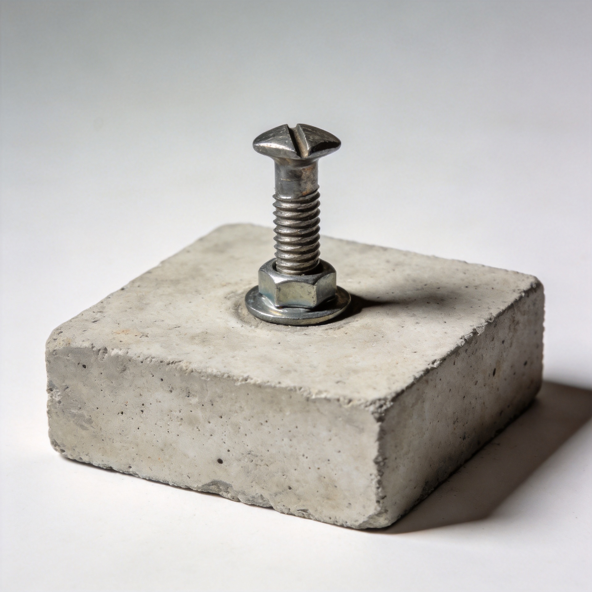
How to Limit Concrete Crack Propagation From Anchor Holes in Slabs
A crack beside an Anchor hole is not a cosmetic detail to dismiss. In a slab, drilling removes material, expansion creates local pressure, and service load can add tension, shear, or vibration. If those effects meet an existing shrinkage crack, a thin cover zone, a free edge, or unverified reinforcement, the crack can lengthen. The practical objective is to control the Anchor design and installation process before local damage becomes a structural question.
From a fastener-selection engineer’s perspective, an Anchor is only one part of the connection. The slab thickness, concrete condition, edge distance, hole layout, reinforcement, fixture load path, and approved installation method work together. A well-made Anchor cannot correct an unsuitable location or a hole drilled through a distressed area.
Start by separating a hairline crack from an Anchor design issue
Before drilling, inspect the slab face and underside where accessible. Mark visible cracks, joints, spalls, previous patch areas, penetrations, and slab edges. A hairline surface crack may have a different significance from a crack that crosses the slab, follows an Anchor row, widens under load, or is accompanied by movement, rust staining, or loose concrete. Do not use an Anchor hole as a diagnostic probe in a questionable area.
Ask a simple question: will this Anchor transfer tension, shear, sustained vibration, or a safety-critical load? The higher the consequence of failure, the less appropriate it is to make a field judgment from appearance alone. The engineer of record should review uncertain slab condition, missing drawings, altered loads, reinforcing conflicts, or any crack that is active or extends beyond the immediate hole zone.
Why cracks can grow around an Anchor hole
An Anchor changes how force enters concrete. A tension-loaded Anchor can develop a concrete breakout region; an expansion Anchor also applies radial pressure while it is set. Near an edge, corner, opening, joint, or neighboring Anchor, there is less concrete available to distribute that stress. Tight spacing may make individual stress zones interact. Overdriving a mechanical Anchor, using the wrong bit diameter, or applying torque beyond the selected system’s instructions can add damage at the hole mouth or deeper in the embedment zone.
Crack propagation is rarely caused by one variable. It is more often a combination of thin slab geometry, low-strength or deteriorated concrete, a crowded Anchor pattern, drilling vibration, and a load path that was not checked. In practical terms, treat the first visible crack as a reason to pause and verify the whole installation condition rather than merely filling the crack and continuing.
Choose the Anchor system for the condition, not just the catalog load
Wedge anchor: useful only where expansion is appropriate
A wedge anchor is commonly used in sound, adequately thick concrete when the approved design supports its edge distance, spacing, embedment, and load case. Its expansion action means it deserves careful attention near cracks and free edges. Do not assume that increasing a wedge anchor size or tightening it harder provides a safer answer; the chosen Anchor must match the manufacturer’s published installation and design data for the actual slab condition.
Sleeve anchor: consider the base material and fixture details
A sleeve anchor can suit some solid masonry and concrete applications, but it is not a substitute for an engineered review of a cracked slab. Its expansion sleeve still loads the hole wall. Confirm the selected sleeve anchor’s approved base material, hole size, embedment, fixture thickness, and tightening procedure. Where crack sensitivity is high, the project design may call for a different Anchor approach instead.
Drop in anchor: verify setting depth and usable section
A drop in anchor is installed flush or below the surface and requires the correct setting tool and depth. It can be convenient for removable threaded-rod work, yet the same geometry questions remain: is the slab thick enough, is the Anchor clear of vulnerable edges, and can the required hole be drilled without intersecting reinforcement or a deteriorated zone? Do not select a drop in anchor solely because the finished surface needs to stay clear.
The broad term concrete anchor covers systems with different load-transfer mechanisms. For a critical repair or a cracked structural slab, ask the designer to identify the exact Anchor family, performance category, installation condition, and inspection requirements. Adhesive systems, mechanical systems, and cast-in details are not interchangeable.
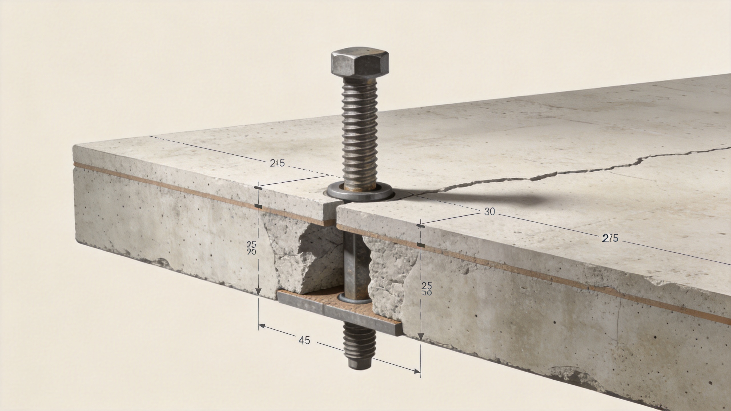
Use a drilling plan that protects the slab
- Locate before drilling. Review drawings and scan as appropriate for reinforcement, conduits, post-tensioning elements, and embedded items. If the slab may be post-tensioned, stop until qualified personnel confirm a safe drilling plan.
- Lay out real edge distances and spacing. Measure from the actual hole center to edges, joints, openings, and other Anchor holes. Do not rely on nominal fixture dimensions when a slot or field adjustment shifts the Anchor pattern.
- Use the specified bit and depth. Match the bit diameter and drilling depth to the selected Anchor instructions. A wandering or oversized hole can reduce engagement and damage the concrete around the Anchor.
- Control drilling technique. Hold the drill square, avoid forcing a dull bit, and pause if the bit suddenly drops, binds, strikes steel, or produces unusual cracking. Repeated hammering at a damaged location can enlarge the problem.
- Clean and inspect the hole. Remove drilling debris by the procedure required for that Anchor system. Inspect the hole mouth for spalling and verify the required embedment before setting the Anchor.
- Set and tighten exactly as specified. Use the designated setting method and torque control where required. Do not use extra tightening to compensate for uncertainty in the hole or slab.
What to do when a crack appears during installation
Stop work at that Anchor location. Photograph and mark the crack, note its direction and approximate length, record the bit size and intended Anchor type, and compare the hole location with edges, joints, reinforcement information, and nearby holes. Do not install a larger Anchor in the same damaged hole as an improvised fix. Do not move the Anchor a short distance without checking whether the revised position changes the fixture load path or violates the approved layout.
A qualified engineer may decide that the condition is superficial, that the Anchor location can be redesigned, that a different approved Anchor system is suitable, or that crack repair and structural evaluation are needed first. The field team’s role is to preserve the evidence and follow the revised detail—not to infer capacity from a torque wrench reading.
A practical slab-anchor checklist
- Confirm the Anchor load, direction, duty cycle, and consequence of failure.
- Verify slab thickness, concrete condition, reinforcement information, edges, joints, and penetrations.
- Use an Anchor system approved for the base material and installation condition.
- Check the specified hole diameter, depth, cleaning method, setting method, and torque before work begins.
- Keep each Anchor within the approved layout; document changes instead of making field substitutions.
- Escalate new cracking, spalling, unexpected steel, or uncertain slab construction to the responsible design professional.
Build crack control into the Anchor decision
The reliable way to limit crack growth around an Anchor hole is to treat location, slab condition, Anchor type, drilling, and load transfer as one decision. A wedge anchor, sleeve anchor, drop in anchor, or other concrete anchor may be appropriate under the right approved conditions, but none should be used to bypass a slab assessment. Start with verified geometry, follow the system instructions, stop at the first sign of damage, and obtain project-specific engineering direction when the slab or load path is uncertain.