EN

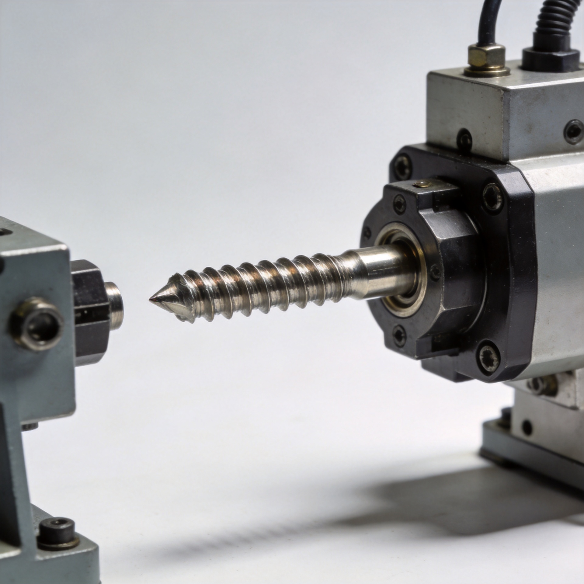
How to Stop Cross Threading When Driving Screws by Machine Feeder
When a screw starts on the wrong axis, the feeder may look innocent even though the failure began before the driver applied meaningful torque. In automated assembly, a cross-threaded screw can damage the mating feature, create an unstable clamp load, and turn a short cycle interruption into a sorting or rework problem. Rather than treating tool speed as the first fix, trace the screw from presentation through the first thread engagement.
From an engineering troubleshooting perspective, most repeatable screw-start problems come from a small group of interfaces: the feeder escape, the pickup point, the driver nosepiece, the part fixture, and the receiving thread. A stable process keeps those interfaces centered while the screw is still free to find its lead thread.
Why a feeder-driven screw cross-threads
Cross-threading means the external thread enters the mating thread at an angle or at the wrong lead. It often begins before the screw has completed its first turn. If the driver then applies torque, the screw may cut across the intended path instead of following it. A finished joint can look seated while carrying uneven or low clamp force.
Three conditions commonly combine in a machine-feeder station:
- Off-axis presentation: The screw leaves the feeder, pickup tube, or escapement with more tilt than the driver nosepiece can correct.
- Part movement: The workpiece hole shifts after the screw is presented because a locator, nest, or clamp has play.
- Damaged or unsuitable thread entry: A burr, coating buildup, deformed lead thread, or wrong screw family gives the screw no clean starting path.
Do not assume every abnormal torque trace identifies a driver setting issue. A cross-threaded screw often produces a different rundown shape from a screw that is merely reaching seating torque early. Compare failed parts with known-good parts and inspect the first engaged threads before changing the final torque target.
Start with the screw and mating-thread combination
First confirm that the feeder is presenting the exact screw specified for the joint. Similar-looking fasteners can produce very different starts. A machine screw is intended to mate with a prepared internal thread or a nut, so pitch, diameter, and thread form must match the receiving feature. A wood screw is intended to form or grip in wood-based material; it is not a substitute for a machine screw in a tapped metal or molded threaded insert.
A self tapping screw can form its own mating thread in a suitable pilot hole, but its entry behavior, required axial load, and torque signature differ from a machine screw. A hex screw describes a drive or head style in many purchasing conversations, not a complete threading specification. Before adjusting automation, verify the drawing callout, thread gauge result, coating condition, and batch identity for both the screw and the mating part.
Inspect several screws under magnification. Look for a flattened point, rolled-over first thread, plating nodules, or mixed stock. Then inspect the receiving thread for a burr at the entrance, a damaged insert, chips, or an incomplete tap. If a defect follows one component lot rather than one station, fixture adjustment will not solve the source issue.
Check alignment in the order the screw travels
1. Feeder outlet and escapement
Watch the screw at the final release point. It should arrive consistently oriented and should not bounce, rotate freely, or drag against a worn guide. A feeder that presents a screw head-first but leaves the shank unsupported can allow the screw to enter the driver at a slight angle. Check guide width, air pressure where used, contamination, and wear on the transfer surfaces.
2. Driver bit, vacuum pickup, and nosepiece
The driver must hold the screw concentric with its own axis. A worn bit, weak vacuum pickup, bent blade, or oversized nosepiece can let the screw wobble during descent. With power isolated as appropriate for your procedure, check concentricity and the clearance between the screw shank and the nosepiece guide. The tool should release axial support only after the screw has found the thread.
3. Fixture and part datum
Next, measure the relationship between the driver axis and the actual threaded hole, not only the nominal fixture drawing. Clamp the part as it is clamped during production. Check for part lift, datum contamination, locator wear, and variation caused by incoming components. A fixture can look square when empty yet shift the hole position when the clamp load is applied.
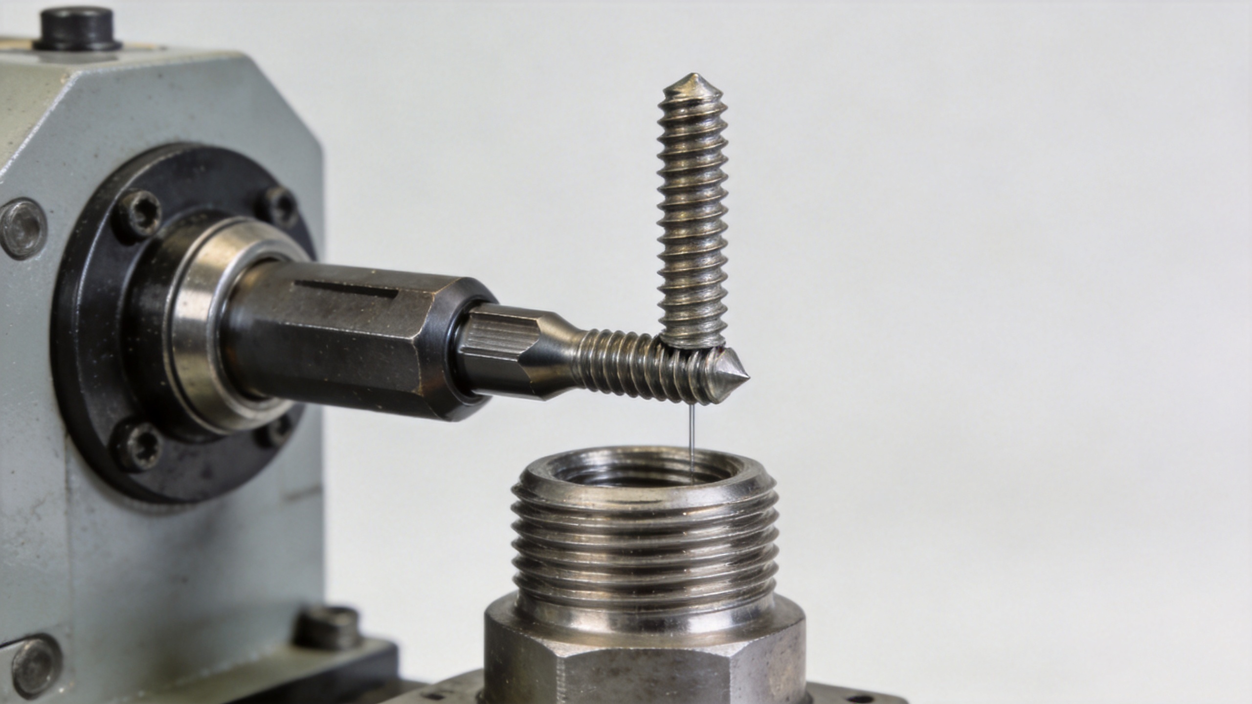
Use a controlled starting sequence
For a machine screw, the lowest-risk sequence gives the screw a short, controlled opportunity to find the lead thread before full-speed rundown. Bring the driver down squarely, apply enough axial support to keep the screw engaged, and use a reduced initial speed if the tool controller allows it. The goal is not a universal speed value; it is a repeatable start that does not force a misaligned screw into the mating thread.
Where the joint allows it, a brief reverse motion can help the screw settle on the thread start before forward rotation. Validate this on representative parts because it is not suitable for every joint or every self tapping screw. Treat it as a diagnostic and process option, not a substitute for correcting poor alignment.
- Run a short sample at slow initial speed and inspect the first threads.
- Compare axial position and torque-versus-angle behavior with good cycles.
- Adjust one factor at a time: fixture location, nosepiece support, initial speed, or axial force.
- Repeat the check with parts from normal production variation, not only a hand-selected sample.
Read the failure pattern before changing torque
A useful station log records the screw type, lot, part lot, station, operator shift, and observed rundown behavior. If failures occur at one station, inspect feeder-to-driver alignment and fixture repeatability first. If they appear across stations with one screw lot, inspect the screw lead threads and dimensions. If they follow one mating component lot, gauge the internal thread and entry feature.
High torque alone is not proof of cross-threading. A screw can reach high torque because it bottoms out, hits a seating surface, forms a thread, or encounters a contaminated hole. Pair the torque trace with a visual inspection and, where appropriate, a strip-and-inspect check. The first damaged thread tells a more useful story than a final torque number by itself.
A practical recovery checklist
- Quarantine the affected screw and mating-part lots until the first-thread condition is understood.
- Check the feeder exit, driver axis, nosepiece, and fixture datum in that order.
- Verify that the specified machine screw, wood screw, self tapping screw, or hex screw configuration matches the joint design.
- Inspect failed and good assemblies side by side; do not judge only by a seated head.
- Document the approved start speed, axial support, and inspection frequency after the correction is verified.
The durable fix is usually a centered screw, a clean lead thread, and a fixture that holds the mating feature where the driver expects it. When those basics are controlled, the feeder becomes a repeatable part of the assembly process rather than a source of uncertainty.