EN

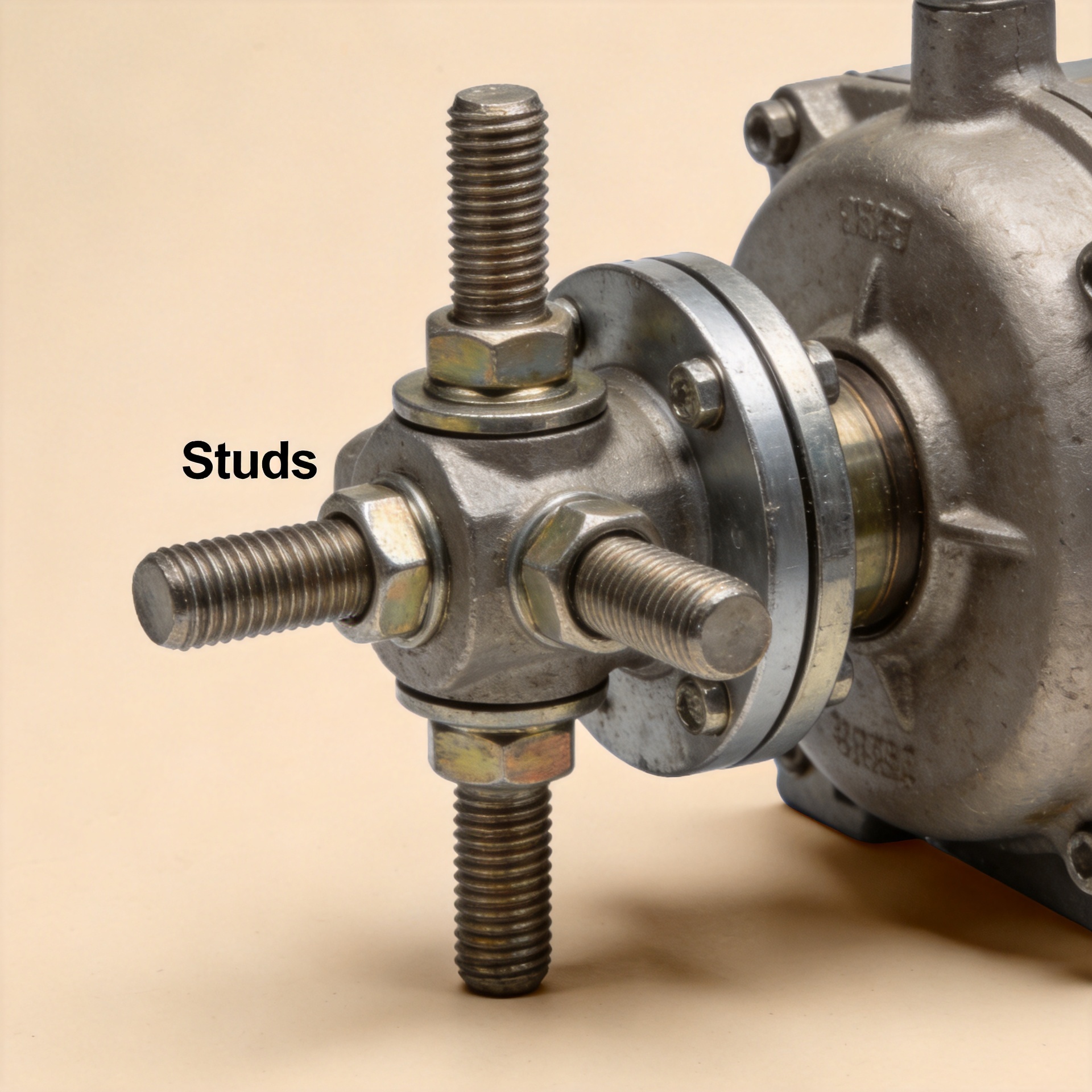
How to Stop Stud Backout in Vibration Loaded Compressor Assemblies
When a compressor assembly develops a loose cover, cylinder, bracket, or flange connection, the visible symptom is often a stud that has backed out. The root cause is usually more specific: the joint has lost enough clamp load for relative movement to begin. Once that movement reaches the thread contact zone, a threaded stud can rotate in the loosening direction during repeated vibration. Replacing the part without correcting the joint is likely to repeat the failure.
From a fastener-selection engineer’s perspective, the useful starting point is not “which locking product should we add?” It is: where did preload go, what is moving sideways, and is the double ended stud working with the joint geometry rather than against it? That sequence is especially important in compressors, where pulsation, rotating equipment vibration, thermal cycling, and maintenance access can all affect a joint differently.
Backout starts with clamp-load loss, not with the visible thread
Studs hold a joint together by stretching slightly as they are tightened. That elastic stretch creates clamp force across the mating faces. If the external forces remain below the friction capacity generated by that clamp force, the parts stay still and the connection has a good chance of retaining torque. If transverse loading overcomes that friction, however, the clamped parts can slip microscopically. Relative motion at the bearing surface and mating threads is the condition associated with rotational self-loosening in vibration-loaded joints.
In practical troubleshooting, three paths commonly reduce preload before a threaded stud turns:
- Embedment and seating loss: paint, burrs, plating irregularity, surface roughness, or imperfectly seated washers compress during early operating cycles.
- Thermal or material relaxation: temperature changes and local yielding can change the force distribution in the joint.
- Insufficient initial tension or uneven tightening: an apparently correct torque may not create the intended clamp load when friction, lubrication, or tool control varies.
It is tempting to respond by specifying the highest-strength Studs available. That can miss the mechanism. A higher strength grade may be appropriate after an engineering review, but it does not by itself remove joint slip, poor thread engagement, or a torque process that cannot produce repeatable preload.
First identify which contact region is moving
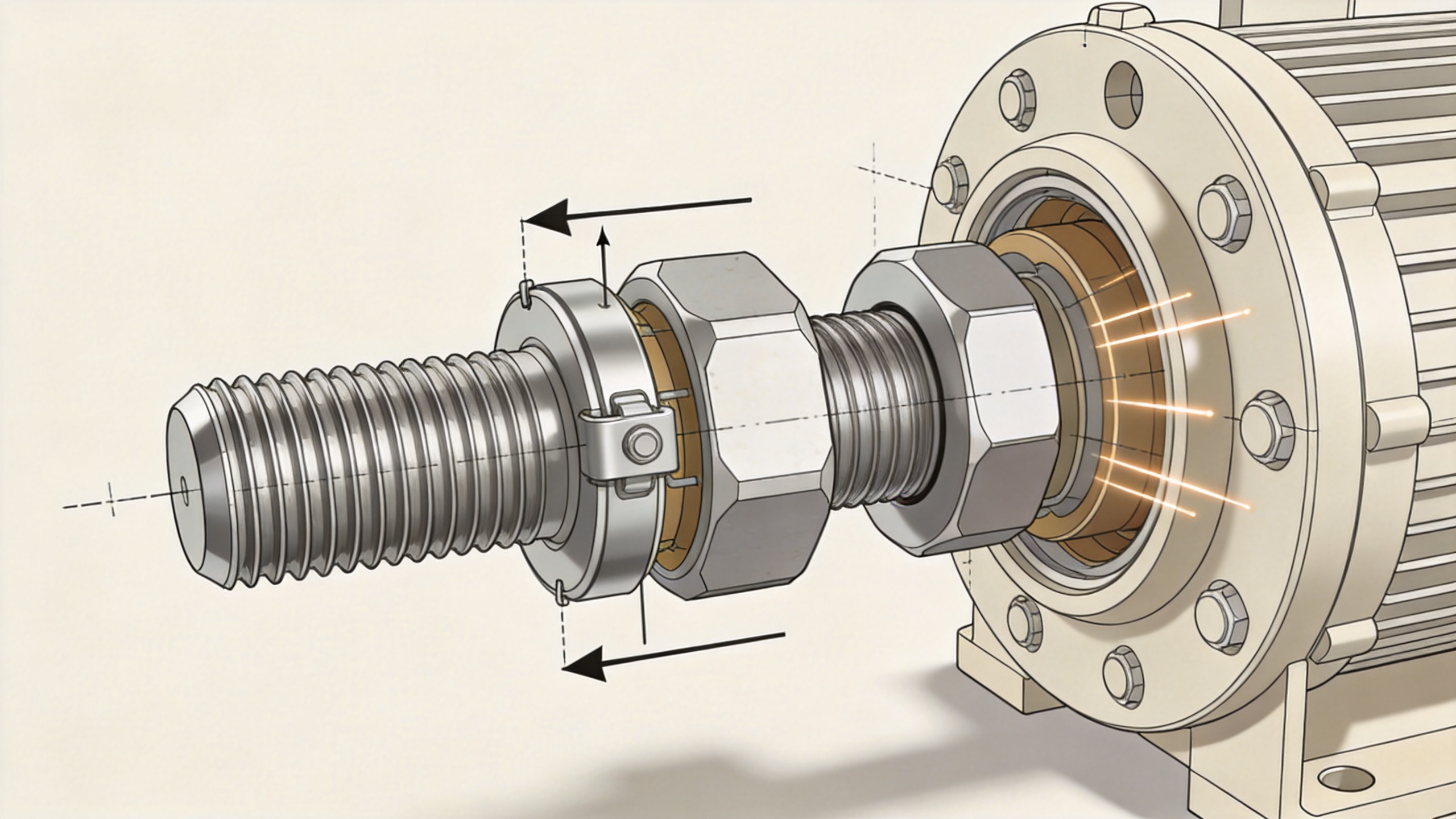
A double ended stud introduces two threaded contact regions: the installed end in the base component and the nut end that clamps the external part. Either contact region can become the problem. Mark the stud, the housing, and the nut before disassembly, then inspect witness marks after a controlled run if site procedures allow. This helps distinguish a stud unwinding from the tapped component from a nut rotating on the exposed end.
Check the installed end
For the end seated in a compressor casing or support, confirm thread cleanliness, actual engagement length, bottoming clearance, and whether the stud was driven using a method that damaged threads or applied unintended torsion. A threaded stud that bottoms before its intended seating condition can feel tight while providing poor resistance to cyclic movement. If repairs have introduced inserts, coatings, or changed thread depth, reassess the engagement rather than assuming the original assembly torque still applies.
Check the clamped end
At the nut end, inspect flatness of washers and faces, clearance-hole condition, local fretting, and whether the clamped stack has enough stiffness. A long, flexible stack or a soft contact layer can lose a meaningful share of its preload as surfaces settle. In contrast, an overly short effective grip can make the system less forgiving of small settlement changes. The right balance depends on the actual compressor joint, not a generic rule.
Build a retention plan around the joint, not a single product claim
The following sequence gives maintenance and design teams a defensible way to decide what to change.
- Define the load direction. Record whether vibration is mainly axial, transverse, or a combination. Transverse motion deserves particular attention because it can drive relative movement across the joint.
- Set the preload method. Use a documented tightening method compatible with the specified Studs, lubricant condition, nut style, and access. Torque alone is an indirect control; where the joint is critical, consider an engineering-approved verification method that better reflects tension or elongation.
- Correct the bearing surfaces. Remove burrs and unstable coatings from the clamped contact surface as permitted by the design. Use hardened or specified washers where the design calls for them, and make sure the bearing faces are parallel.
- Confirm thread engagement. Match the threaded stud length, pitch, and installed depth to the parent material and loading condition. A double ended stud should have an installation geometry that does not create a false stop or leave insufficient effective engagement.
- Select a compatible anti-loosening method. Prevailing-torque nuts, mechanical locking features, adhesive threadlockers, or other retention approaches can be useful, but each has temperature, serviceability, surface-condition, and installation constraints. Choose one after identifying which contact region needs retention.
- Validate under representative vibration. A transverse-vibration evaluation, often discussed in relation to Junker-style testing, can compare joint configurations under cyclic movement. The test setup, preload, materials, and temperature should resemble the application closely enough to support the decision.
Where threaded studs, welding studs, and stud bolts fit
Terminology can hide an important design decision. A threaded stud is often selected when one end must remain in a component while the other receives a nut. A double ended stud can help when repeated service would otherwise wear a tapped base thread, but its installed-end geometry must still be controlled. A welding stud is a different joining approach and needs evaluation of weld quality, base material, and vibration path; it is not an automatic substitute for a removable threaded connection. A stud bolt is typically a fully threaded rod-like fastener used with nuts on both ends, often in flange applications. The term alone does not determine whether the joint will resist backout.
For compressor work, do not substitute among these forms simply because their diameters look similar. Compare the load path, service access, thermal exposure, material compatibility, and the required assembly procedure. The outcome should be a joint specification, not merely a part-number change.
Installation controls that stop recurring rework
Many repeat failures trace back to an uncontrolled installation variable. Create a work instruction that identifies the fastener grade and finish, lubricant or threadlocker condition, washer orientation, tightening sequence, target method, and inspection point. If a locking compound is used, document surface preparation, setting-time requirements, and disassembly expectations; product behavior can change significantly when oil contamination or elevated temperature is present.
It also helps to separate one-time settling from ongoing vibration loss. After a defined run-in interval approved by the equipment owner, inspect for movement and clamp-load indicators rather than repeatedly applying more torque without diagnosis. Re-torquing a joint that is slipping because of a damaged face or shallow engagement can conceal the cause while increasing the chance of thread damage.
A practical inspection checklist
- Verify the failure location: installed stud end, nut end, or movement between clamped parts.
- Compare actual thread engagement and free depth with the drawing and repair history.
- Look for fretting, polished contact patches, crushed coatings, or uneven washer marks.
- Check whether the tightening procedure matches the fastener condition used in service.
- Review vibration direction, temperature cycle, and nearby rotating or pulsating loads.
- Test a proposed locking approach on a representative assembly before applying it across a fleet.
Closing recommendation
Stopping stud backout in a vibration-loaded compressor assembly means retaining preload and limiting relative movement. Start by locating the moving interface, then correct engagement, bearing surfaces, joint stiffness, and tightening control before adding a retention feature. For critical equipment, verify the complete assembly under representative vibration rather than relying on a label or a single tightening value. That process gives Studs, nuts, and the surrounding joint a defined role in a repeatable reliability plan.