EN

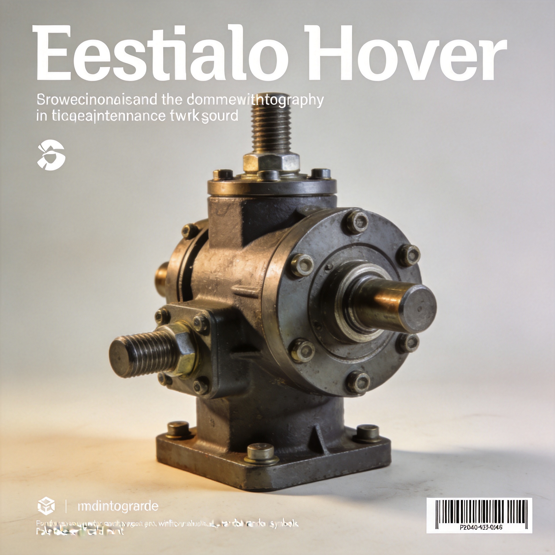
How to Solve Fastener Backout in Equipment Under Thermal Cycling
A fastener that walks loose after repeated heat-up and cool-down cycles is usually signaling a joint-system issue, not simply a torque problem. In production equipment, the temperature swing changes the relationship between the bolt, the clamped parts, coatings, and bearing surfaces. If clamp load falls, a fastener can experience small movements that eventually turn into visible backout, leakage, alignment drift, or an unplanned shutdown.
As a practical maintenance rule, start with evidence rather than retorquing the same fastener repeatedly. Record the joint location, temperature range, shutdown history, torque method, and the sequence in which backout appears. That record helps separate thermal relaxation from vibration, embedment, thread damage, or an assembly-process error.
Why a Fastener Loses Clamp Load During Thermal Cycling
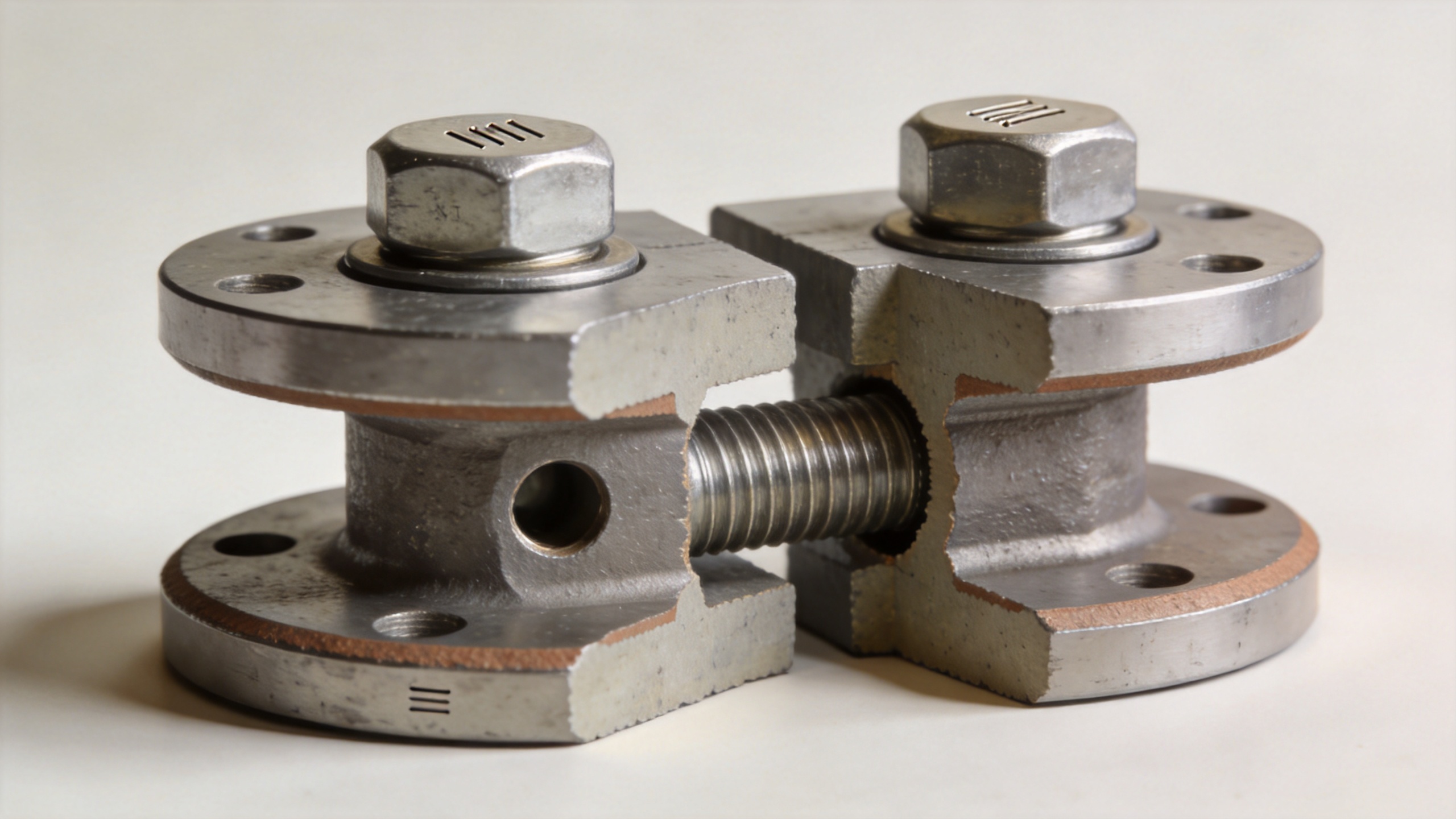
A bolted joint works because the fastener stretches and compresses the clamped stack. The resulting preload keeps the parts together. During a temperature excursion, every component expands or contracts according to its material, length, and local temperature. If the fastener and the clamped members do not move by the same amount, preload changes. A joint may feel secure at installation temperature yet lose useful clamp load after several operating cycles.
Material pairing matters. Aluminum and stainless steel, for example, have different coefficients of thermal expansion; one engineering source cites approximately 23.6 ppm/°C for aluminum and 16.3 ppm/°C for stainless steel. That comparison is illustrative rather than a design calculation, but it shows why a mixed-material joint deserves more attention than a same-material joint. A stainless fastener can be suitable for corrosion exposure, while still requiring a check of expansion mismatch, washer selection, and target preload.
Thermal cycling also exposes settling in the joint. Rough bearing faces, paint, soft gaskets, burrs, and coating compression can flatten after assembly. This embedment reduces the stretch in the fastener. Once the joint no longer has enough clamp force, vibration or side loading can create microscopic slip. That is when a threaded fastener may rotate loose even if the original installation torque looked correct.
Diagnose the Failure Mode Before Selecting a Fix
Do not treat every loose fastener as an identical event. Use a structured inspection to establish which force is changing the joint.
- Map the pattern. Note whether backout occurs at hot zones, near heaters, beside process piping, or only on one side of a frame. A location pattern often points to a temperature gradient or joint stiffness difference.
- Check temperature history. Compare normal operating temperature, startup rate, cooldown rate, and any overshoot. A fastener located close to a heat source may see a different temperature than the supporting structure.
- Inspect the clamped stack. Look for witness marks, polished contact patches, fretting debris, compressed coatings, cracked washers, gasket extrusion, or elongated holes. These observations help identify movement rather than simple under-tightening.
- Verify the installation method. Confirm the specified lubricant condition, tool calibration, tightening sequence, and torque or angle procedure. Torque is an indirect indication of preload, so a changed surface condition can change the result.
- Measure what is practical. For critical joints, use a documented preload-verification method appropriate to the assembly. Recheck after a representative thermal cycle rather than relying only on an ambient-temperature reading.
Correct the Joint, Not Just the Symptom
Set a preload that fits the operating condition
The fastener must supply enough clamp load to keep the joint interfaces from separating or slipping through the expected thermal and service load range. Review the assembly drawing, material grades, bearing area, and safety requirements with the responsible engineer. Raising torque without checking thread capacity, friction, gasket behavior, or yielding can trade backout for damage. A mechanical fastener selection should be tied to the whole joint, including nut, washer, surface finish, and tightening method.
Reduce differential movement in the stack
Where thermal mismatch is the main driver, evaluate the materials and geometry together. Longer grip length can change joint compliance; a suitable washer arrangement can spread bearing stress; and a revised spacer or sleeve material can alter how the stack responds. The appropriate choice depends on load path and temperature, so validate a change on an instrumented or closely monitored assembly before applying it fleet-wide.
Address embedment and bearing-face condition
Remove burrs and unstable coatings from bearing interfaces where the joint specification permits. Use flat, compatible bearing surfaces and make sure the fastener head or nut seats squarely. If a soft layer is required, include its compression behavior in the joint design. A custom fastener or custom washer geometry may be appropriate when standard bearing dimensions do not support the required stack, but its material and thread form still need engineering review.
Add rotation resistance only after preload is understood
Thread-locking features, prevailing-torque nuts, wedge-locking washer systems, safety wire, or other retention methods can help when a joint sees vibration after thermal preload loss. They are not substitutes for clamp load. Choose a retention method that remains compatible with temperature, service fluids, inspection practice, and maintenance access. If the joint must be opened often, document the reuse limits for the selected fastener and locking element.
Use a Controlled Retorque and Validation Plan
A one-time retorque can hide an unresolved issue. Instead, establish a controlled plan. First, replace damaged threads, distorted washers, and parts showing fretting or severe corrosion. Assemble the joint with the specified condition and sequence. Mark the fastener and adjacent surface so that later rotation is visible. Then operate the equipment through a representative heat-and-cool cycle and inspect at defined intervals.
The acceptance criteria should be specific: no witness-mark rotation, no loss of required function, no new leakage, and no unacceptable change in the approved verification measurement. If movement continues, compare the result with the inspection record. Continued rotation near a heat source points toward temperature distribution or expansion mismatch; movement across many joints may point toward an installation process or stack-surface issue.
Build Thermal-Cycle Checks Into Maintenance
Equipment teams get more useful results when thermal-cycle checks are part of planned maintenance. Keep a joint register for locations where a fastener is exposed to repeated startup and shutdown cycles. Include material combination, temperature zone, tightening specification, locking method, inspection interval, and previous findings. This turns a recurring loose-fastener complaint into a traceable reliability task.
For new or modified equipment, review critical joints before commissioning. Confirm that the specified fastener material, clamped materials, expected temperature range, and service loads were considered together. Where conditions are uncertain, use a pilot assembly and inspect it after early thermal cycles. That approach gives maintenance and engineering teams a basis for refining the joint before routine operation magnifies a small loss of clamp load.
Key Takeaway
Fastener backout under thermal cycling is usually solved by restoring stable clamp load and limiting relative movement across the full operating temperature range. Diagnose the pattern, inspect the clamped stack, verify the assembly method, and validate the corrected joint after a representative cycle. A fastener retention feature can support the solution, but the durable answer begins with a joint that keeps its preload when equipment heats and cools.