EN

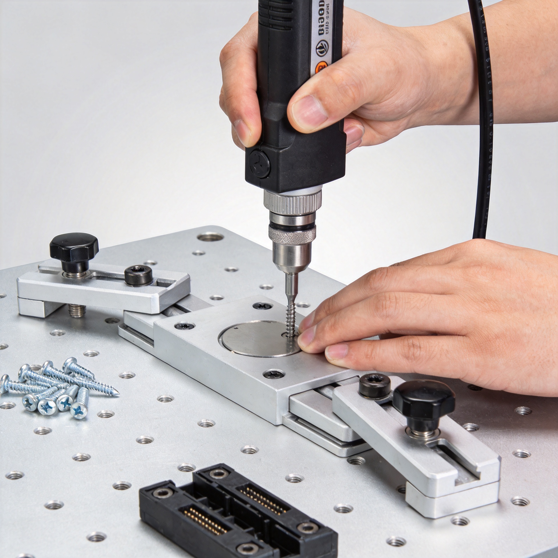
How Can Proper Screw Installation Improve Assembly Quality?
In a production cell, a screw is easy to overlook because it is small, familiar, and inexpensive. Yet the installation of each screw can affect fit, function, rework, and the consistency of the finished assembly. A joint may look acceptable at a glance while carrying too little clamp load, damaging a mating thread, or relying on a tool setting that does not suit the actual stack-up. Proper screw installation turns fastening from a last-step action into a controlled part of the assembly process.
From an assembly-floor perspective, the useful question is not simply, “Was the screw tightened?” It is: was the correct screw installed into a prepared joint, with a qualified method, and with evidence that the process stayed in control? The answer influences assembly quality long after the operator moves to the next station.
Why screw installation has such a large effect on assembly quality
A screw joint works by creating clamp force between components. That force depends on more than the setting shown on a driver. Thread condition, surface finish, lubrication, washer use, joint stiffness, screw geometry, and run-down speed can all change the relationship between applied torque and the force achieved in the joint. For that reason, a torque value should come from the applicable drawing, engineering specification, or validated work instruction; it should not be copied from an unrelated assembly.
When installation is inconsistent, the same screw type may produce different outcomes across a batch. Under-tightening can allow relative movement, noise, leakage, or loosening under vibration. Excessive tightening can strip threads, deform softer material, damage a head or drive recess, or overload a component. Either condition can become a quality issue even when the screw itself meets its purchase specification.
The point matters even more in repetitive work. A small variation in screw installation repeated across hundreds of units can become a measurable source of rework, inspection time, and field-return investigation. Treat the joint as a system rather than judging the screw in isolation.
Start with the right screw type for the joint
Proper installation begins before the tool touches the part. Confirm that the screw type matches the bill of materials and the joint design: diameter, pitch, length, head style, drive recess, material, coating, and strength class all matter. A visually similar screw can have a different thread form or usable thread length, which can change engagement or damage the receiving feature.
Match the screw type to the base material as well. Thread-forming screws, machine screws, and self-drilling screws follow different installation logic. A machine screw entering a tapped metal hole needs clean, compatible threads and adequate engagement. A thread-forming screw needs the pilot feature and material condition specified for that process. If your assembly uses plastic, thin sheet, coated parts, or a joint exposed to vibration, the approved screw type and any washer, locking feature, or thread treatment deserve explicit verification.
Make part identification easy to follow at the workstation. Segregated bins, clear labels, part scanning, and first-piece checks reduce the chance that a screw from a nearby operation reaches the wrong joint. Many mixed-part errors start with packaging or replenishment, not with the tightening cycle itself.
Prepare the joint before driving the screw
Good screw installation is difficult when the mating parts are misaligned. Check that holes are aligned, threads are undamaged, interfaces are seated, and any required washers, gaskets, or spacers are present. Foreign material, burrs, coating buildup, or a cross-threaded start can cause a driver to reach torque without creating the intended clamp condition.
A simple hand-start or controlled low-speed engagement is useful for joints that are prone to cross-threading. It gives the operator a chance to feel whether the screw begins smoothly before the driver applies speed. This may add a moment to the cycle, but it can save more time than removing a damaged screw from a finished assembly.
The tool-to-drive fit matters as well. A worn bit, an incorrect socket, or poor axial alignment can cam out, mark the head, or send side load into the joint. Before a shift, confirm that the selected driver and bit fit the specified screw type and reach the joint without interfering with surrounding parts or fixtures.
Control torque, angle, and the tightening sequence
Torque control is widely used because it is practical, but torque is an indirect indicator of joint tension. Friction at the threads and under the head consumes part of the input. This means the same torque can produce different clamp force when lubrication, coating, surface condition, or prevailing torque changes. Keep those conditions consistent with the validated process, and do not substitute an unapproved lubricant or finish at the line.
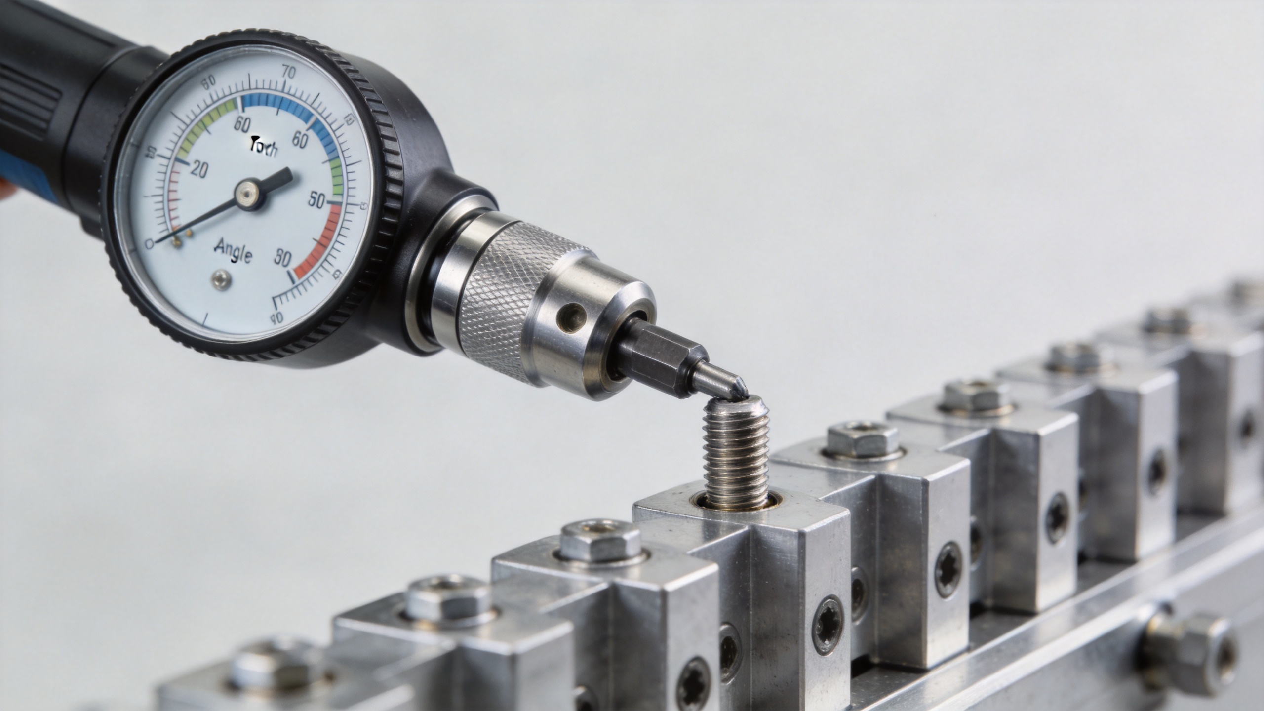
For critical joints, a qualified torque-and-angle process can add useful information. The torque trace indicates resistance as the screw turns, while angle helps show how the joint progressed after seating. In an appropriate process, an unusual torque-angle signature may point to a missing component, damaged thread, misalignment, or a changed friction condition. It is not a universal requirement for every screw, but it can strengthen control where joint risk and production volume justify it.
The tightening sequence needs the same level of attention. Multi-screw covers, flanges, housings, and gasketed joints often need a documented pattern and staged tightening. Tightening one screw fully before neighboring locations are seated can distort the parts or create uneven loading. Operators should follow the released sequence rather than choosing the fastest-looking route.
Use capable tools and clear work instructions
The driver should be suitable for the required range, joint access, and control method. A tool running near the edge of its capable range may not provide the resolution needed for reliable assembly quality. Maintain calibration records, set the tool to the approved program, and protect settings from casual changes. If a tool is replaced, verify that its output and accessories remain appropriate for the screw installation task.
A useful work instruction identifies the screw type, location, tool or program, target and tolerance where applicable, sequence, and any visual acceptance criteria. Photos or diagrams can make orientation and access requirements clearer than text alone. For automated stations, traceable results tied to a unit or batch can help quality teams isolate a process change without treating every finished unit as suspect.
Verify the result without disturbing the joint
Match the inspection method to the assembly risk. A visual check may be enough for a low-consequence enclosure screw, while a load-bearing or vibration-sensitive joint may need process data, sampling, or a defined audit method. Avoid assuming that a single post-installation torque reading proves the original assembly condition. Static friction, seating effects, and the chosen measurement method can influence what that reading means.
Instead, define verification before production begins. The plan may include first-off confirmation, tool data review, periodic samples, thread engagement checks, visual checks for missing hardware, and investigation rules for abnormal traces. When an issue occurs, record the screw type, lot, joint location, tool program, station or operator, and observed condition. Those details support a focused correction rather than a vague conclusion that the fastener was “bad.”
A practical screw installation checklist
- Confirm the released screw type, quantity, and joint location.
- Check that mating parts, holes, threads, washers, and interfaces are ready for assembly.
- Use the approved driver, bit or socket, program, and tightening sequence.
- Start the screw squarely; stop and assess unusual resistance rather than forcing the joint.
- Apply the engineering-defined torque or qualified torque-angle method.
- Complete the specified visual and process-data verification.
- Record exceptions and quarantine suspect assemblies according to the control plan.
Make installation discipline part of the quality system
Proper screw installation improves assembly quality by making the joint repeatable, inspectable, and suited to its actual service conditions. The goal is not to apply the highest torque or to use the most elaborate tool everywhere. It is to use the correct screw, prepared joint, controlled method, and proportionate verification for the application.
When purchasing teams, engineers, and production staff share that discipline, an industrial screw becomes easier to source, install, and trace. The payoff is a steadier assembly process, clearer root-cause analysis, and fewer avoidable surprises at final inspection.