EN

How to Address Screw Bending in Long Reach Fastening Operations
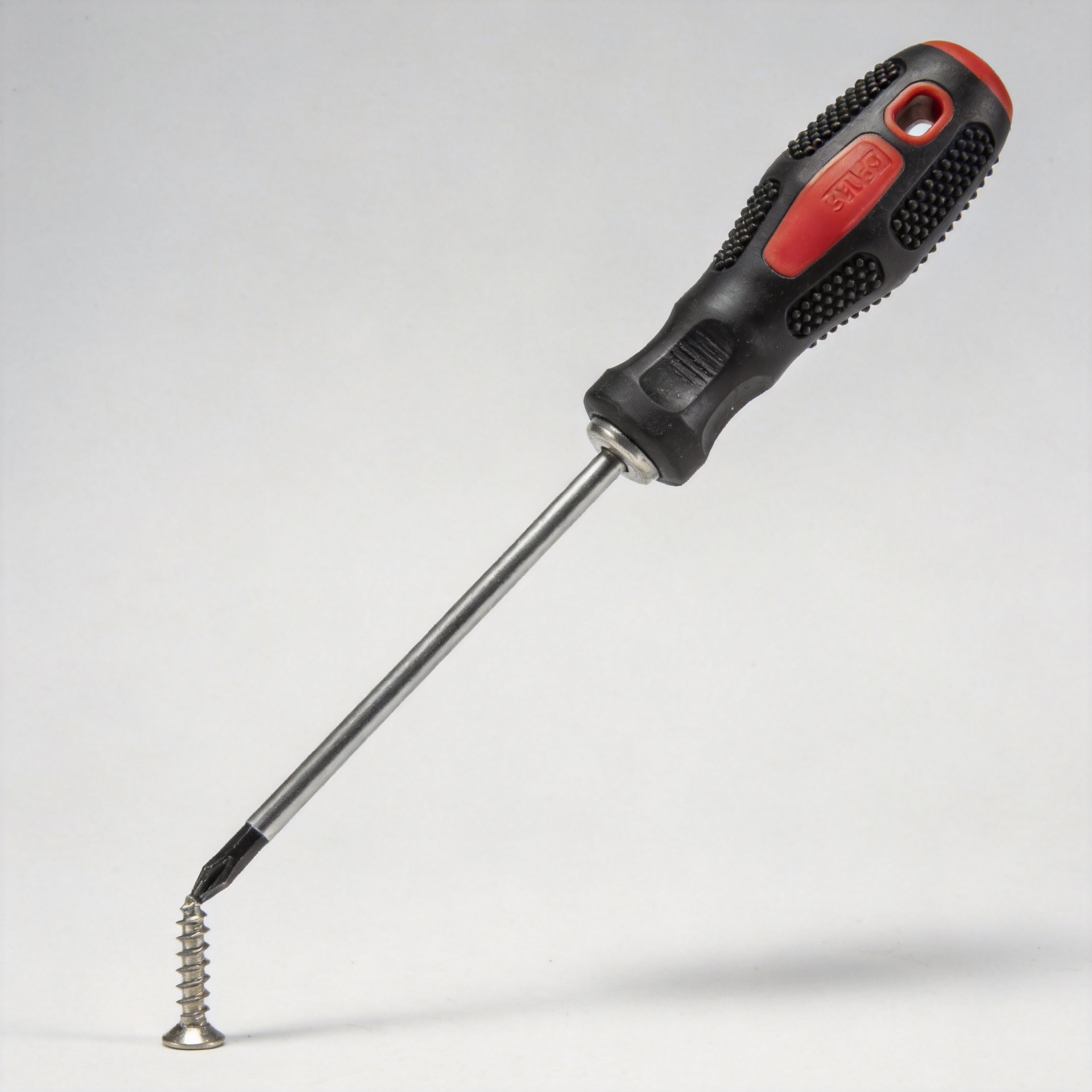
A screw that bends during a deep, recessed, or obstructed installation is rarely a simple material problem. In long reach fastening operations, the screw, bit, extension, workpiece, and operator form one load path. If that path is not close to the screw axis, even a sound fastener can pick up side load before the threads have enough engagement to stabilize it. The visible bend is the late symptom; the useful response is to find where alignment, resistance, or drive control first moved out of tolerance.
From a fastener-selection engineer’s perspective, start with the application rather than with a stronger-looking screw. Note the joint stack, access angle, substrate, required seating depth, driver type, and point in the cycle when bending begins. This approach applies whether the work uses a machine screw in a tapped component, a wood screw in a deep timber assembly, a self tapping screw in formed sheet, or a hex screw where socket access is limited.
Why a Screw Bends During Long Reach Driving
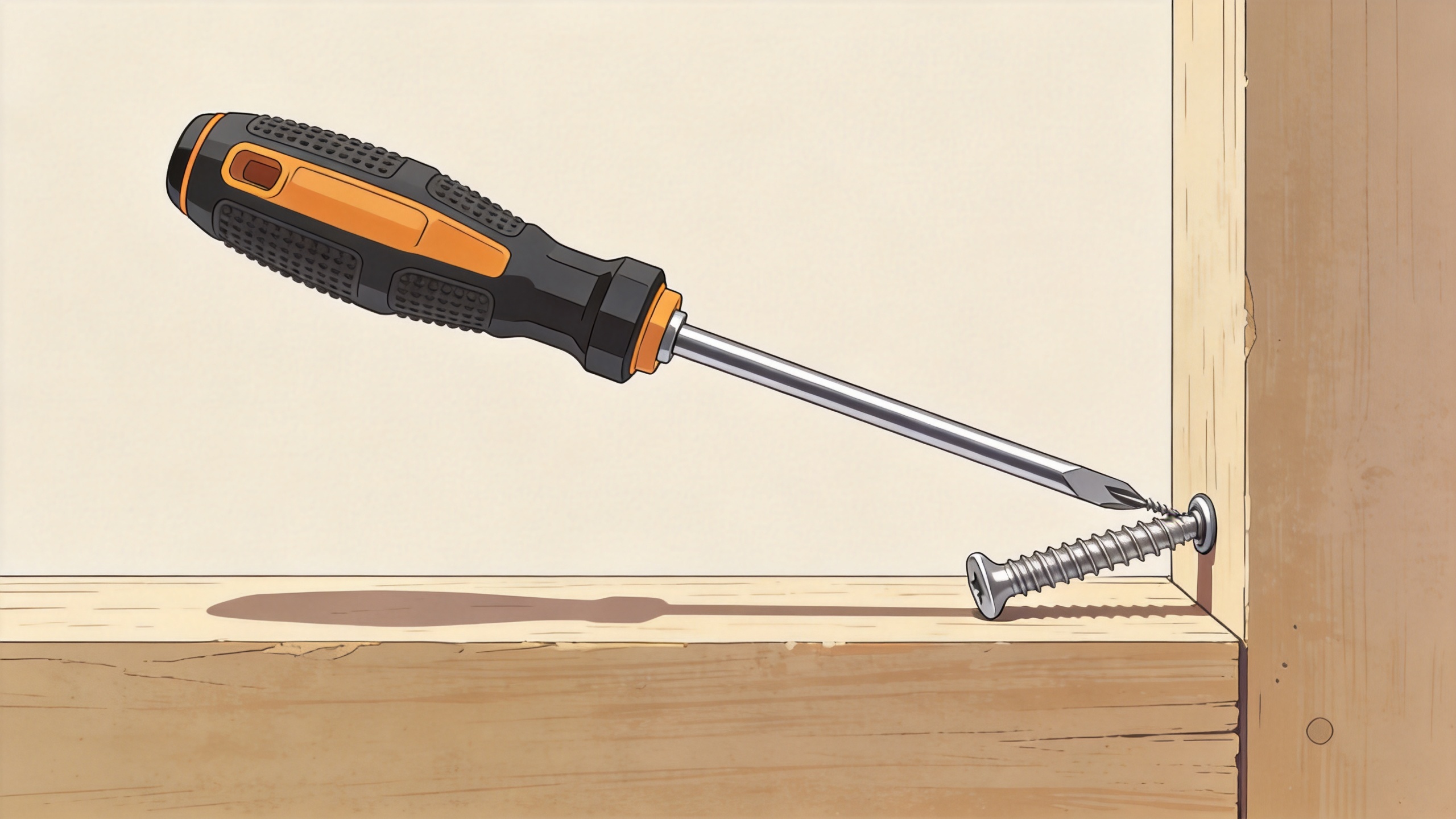
A long screw behaves more like a slender column while it is being driven. Before the head seats and the threads gain stable purchase, sideways force can create a bending moment along the exposed length. The farther the driver is from the work surface, the more a small angular error can turn into noticeable side load at the screw head.
Four conditions often appear together:
- Off-axis engagement: The bit enters the recess at an angle because an extension wobbles, the fixture blocks access, or the operator cannot see the joint.
- High starting resistance: An undersized or poorly located pilot hole, damaged mating thread, debris, coating buildup, or material variation raises drive torque before the screw is supported.
- Inadequate bit retention: A worn bit, a shallow engagement, or a mismatched drive profile lets the driver push sideways on the head.
- Uncontrolled driving energy: High speed or an aggressive clutch setting can load the screw faster than the operator can correct alignment.
The first instinct is often to increase screw diameter or hardness. That can help in a verified strength shortfall, but it does not correct an angled tool path. It may also increase insertion torque and transfer the same problem to the driver, head recess, or receiving material.
Diagnose the Bend Before Changing the Screw
Collect a small sample of failed and successfully installed screws from the same operation. Mark the direction of each bend relative to the tool and the access opening. If bends repeatedly point in one direction, inspect the extension, guide, fixture clearance, and operator approach from that side. Random bend directions point more often to inconsistent starting conditions, damaged bits, variable pilot preparation, or mixed hardware.
Next, determine when the screw bends. A bend near the point usually indicates trouble entering the hole or forming the first thread. A bend near mid-length may indicate the exposed shank is being driven off axis. A bend near the head after partial seating may indicate the driver is slipping or the head is contacting an edge of the access opening. This simple timing check narrows the corrective action without treating every screw as a material defect.
Set Up the Joint for Straight Screw Entry
Verify the receiving feature
For a wood screw application, use a pilot strategy suited to the species, moisture condition, screw geometry, and required holding performance. A common starting principle is to relate the pilot hole to the screw’s core diameter rather than its full threaded outside diameter, then validate the size through a controlled trial. The hole must also be perpendicular to the intended screw axis. A correctly sized hole drilled at the wrong angle still creates side load.
For a machine screw, check the tapped thread with the drawing and the applicable thread standard. Look for cross-threading, damaged lead threads, burrs, paint, chips, or mislocated holes. For a self tapping screw, confirm the sheet thickness, preformed-hole condition, and point style are compatible. Do not force a screw through a blocked or uncertain feature merely because the first few parts appeared acceptable.
Reduce lateral force at the driver
Use a bit that fully matches the recess and replace bits that show rounded edges, reduced retention, or visible wear. Where reach is long, inspect the extension and adapter for runout and play. A rigid extension can transmit torque well but still steer the screw if it is not supported close to the work. A guide sleeve, nosepiece, fixture bushing, or custom access guide can keep the driver axis near the screw axis during the vulnerable starting turns.
If a hex screw is driven through a restricted opening, check that the socket or wrench has clearance around the head. Contact between the tool and the surrounding structure can tilt the tool as torque rises. The correction may be an access change, a different tool length, or a revised assembly sequence—not a different screw alone.
Control the Driving Sequence
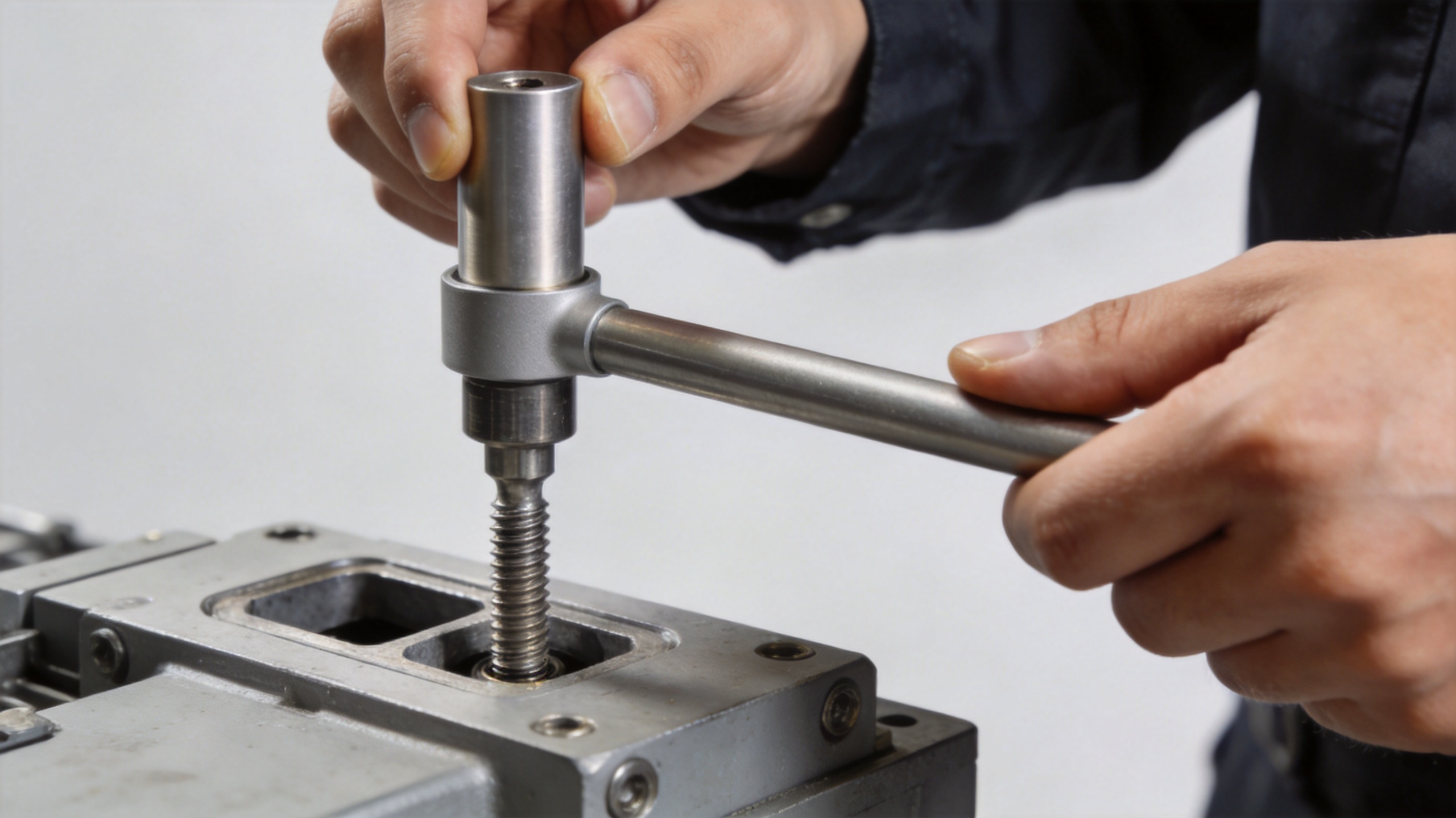
Long-reach fastening benefits from separating thread start from final seating. Start the screw at low speed with light, axial pressure and confirm that it has taken several stable turns. Then increase speed only if the tool remains centered and torque is behaving as expected. Use a torque-controlled tool or clutch setting that fits the joint specification, and validate the setting with the actual reach accessory installed.
- Position the tool square to the joint and support the extension if access permits.
- Engage the bit fully before applying drive force.
- Start the screw slowly and watch for wandering, chatter, or rising resistance.
- Stop immediately if the screw begins to lean; back it out and inspect the receiving feature rather than trying to straighten it in place.
- Seat and verify the joint using the required torque, depth, or flushness criterion.
This sequence may add seconds to a trial build, but it exposes whether the issue is preparation, access, or tool control. On a repetitive line, those observations can become a short work instruction with a defined bit-change interval and a go/no-go check for the guide or fixture.
Choose the Right Escalation Path
Escalate to fastener or joint redesign when alignment and feature checks are sound but bending persists under normal drive conditions. Compare the specified screw length, unthreaded shank, point type, head style, drive recess, material grade, and coating against the actual joint. A shorter free span, a revised pilot feature, a different point, or a supported access method may reduce bending without changing the load requirement. Any change to a critical joint should be reviewed against the assembly drawing, applicable standard, and validation plan.
Also separate a genuine screw-quality concern from a process problem. Retain lot information and inspect suspect fasteners for straightness, dimensional consistency, thread damage, and head recess condition. If only one incoming lot behaves differently under the same validated setup, document the evidence for supplier review. If failures follow one station or one access angle, focus first on tooling and workholding.
Long Reach Fastening Checklist
- Confirm the screw type, length, drive recess, and receiving feature match the approved joint.
- Check pilot holes or tapped threads for location, angle, debris, and damage.
- Inspect the bit, extension, adapter, and guide for wear, play, and clearance.
- Start slowly, maintain axial force, and stop at the first sign of side deflection.
- Record bend direction, station, lot, and insertion stage to isolate repeatable causes.
Addressing screw bending is therefore less about one universal hardware change and more about managing the entire installation path. When the screw starts straight, the receiving feature offers controlled resistance, and the driver stays aligned through seating, long-reach fastening becomes easier to repeat and easier to troubleshoot.